
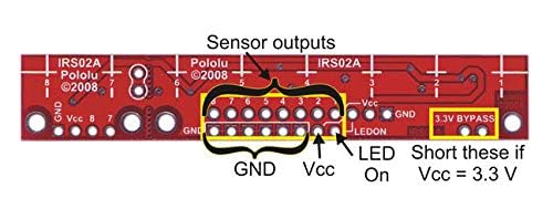
8RC Line Following Reflectance IR Sensor Array
₹413
In stock
- Operating voltage: 3.3 to 5V
- Current supply: 100mA
- Output voltage range: 0V to supplied voltage
- Output format: 8 digital I/O compatible signal
- Sensing distance: 3mm
- Maximum sensing distance: 9.5mm
Description
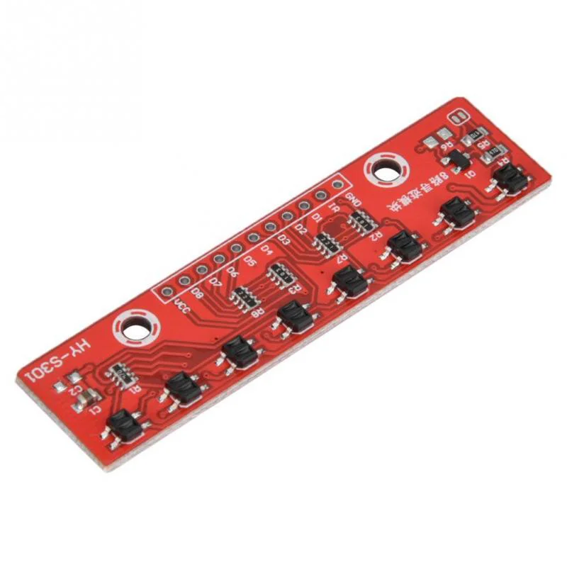
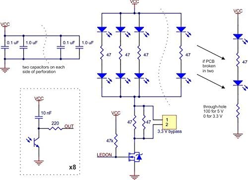
The 8RC Line Following Reflectance IR Sensor Array (QTR-8RC architecture) is an optical reflectance sensor designed specifically for competitive line-following and grid-navigating autonomous robots. Instead of producing variable analog voltages, each phototransistor uses an onboard capacitor to create an RC decay circuit. By timing how long it takes for the capacitor voltage to discharge through the phototransistor, microcontrollers read precise surface reflectance values using digital GPIO pins alone.
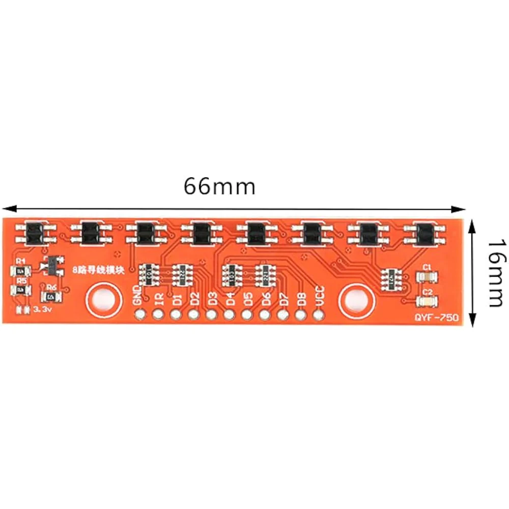
The array mounts 8 infrared emitter/receiver pairs across a compact 75 mm board width. Because all 8 channels can be sampled in parallel using digital pin timing (such as the standard Arduino QTRSensors library), developers get sub-millimeter position feedback to feed directly into proportional-integral-derivative (PID) motor control loops. An integrated MOSFET switch allows setting the LED driver gate LOW to disable IR emission for power conservation or ambient IR calibration.
Technical Specifications
| Parameter | Technical Detail |
| Sensor Type | RC Discharge-Timing Reflectance Sensor Array |
| Number of Channels | 8 Independent IR Emitter / Phototransistor Pairs |
| Sensor Pitch (Spacing) | 9.525 mm (0.375 inches) Center-to-Center |
| Operating Voltage Range | 3.3V to 5.0V DC |
| Supply Current | ~100 mA (Active) | < 1 mA (LEDs Disabled via MOSFET) |
| Output Type | Digital RC Decay Time (Digital I/O Measurable, No ADC Required) |
| Optimal Sensing Distance | 3.0 mm (0.125 inches) |
| Maximum Sensing Range | 9.5 mm (~0.375 inches) |
| LED Control Pin (LEDON) | Onboard MOSFET (Pull LOW to turn OFF IR LEDs) |
| Board Dimensions | ~75 mm × 12.7 mm × 3.2 mm (~3.1 g) |
Pinout & Wiring Interface
+-----------------------------------------------------------------------+
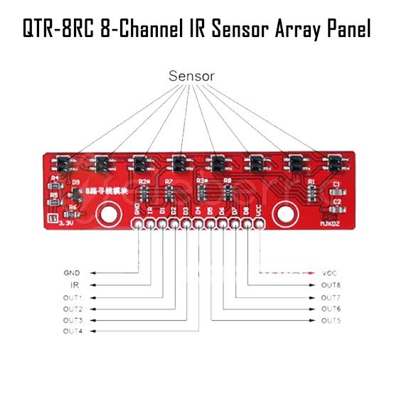
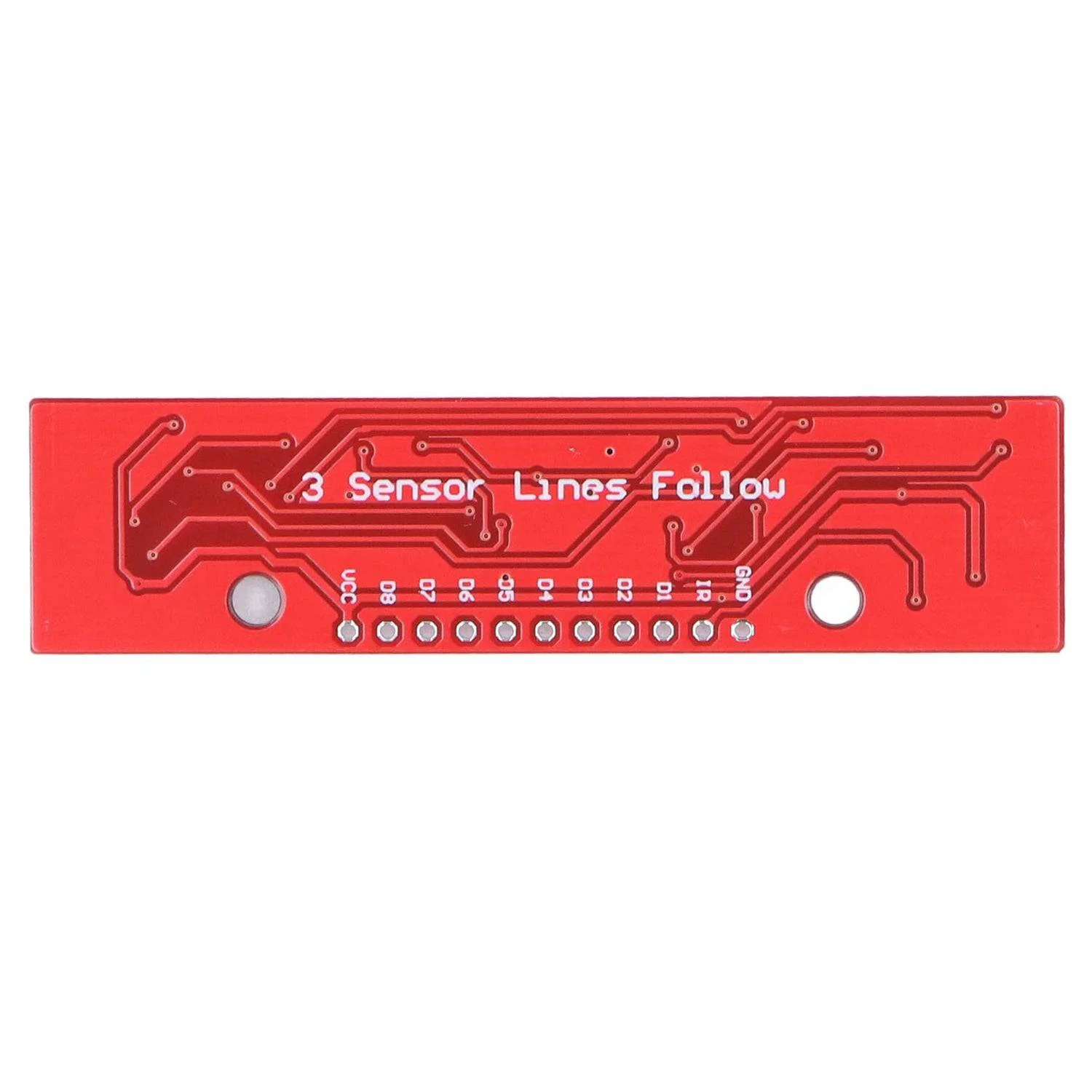
| [LEDON] [OUT1] [OUT2] [OUT3] [OUT4] [OUT5] [OUT6] [OUT7] [OUT8] [GND] [VCC] |
| |
| (IR1) (IR2) (IR3) (IR4) (IR5) (IR6) (IR7) (IR8) |
+-----------------------------------------------------------------------+
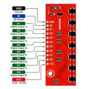
| Pin Name | Function | Description |
| VCC | Power Input | Connect to +3.3V or +5V DC power supply rail. |
| GND | System Ground | Common Ground connection. |
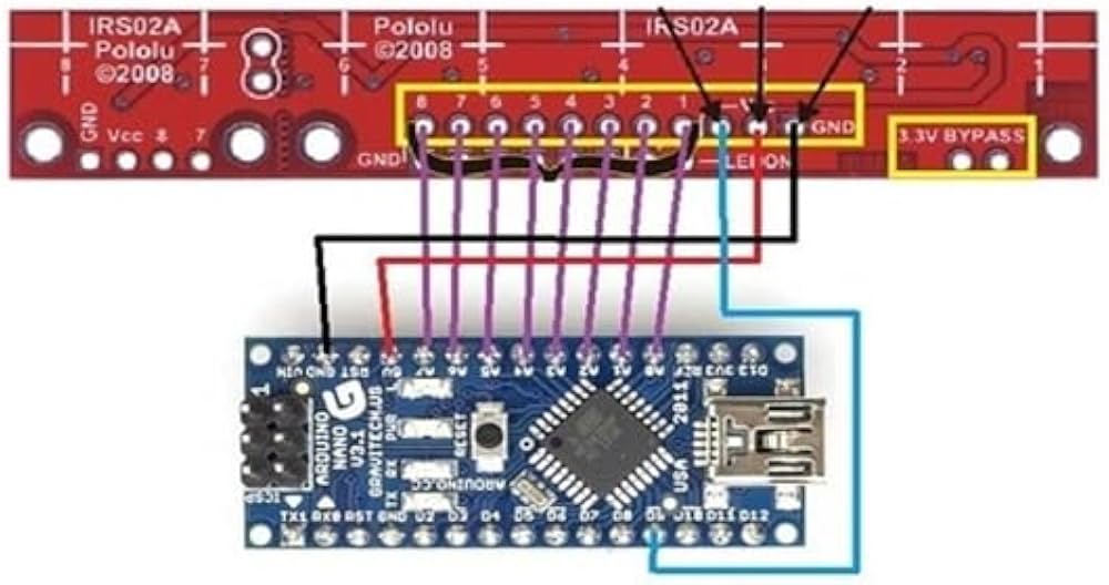
| OUT1 – OUT8 | Digital Sensor Outputs | Connect to digital I/O pins. Measure I/O line discharge time to determine line reflectance. |
| LEDON | IR LED Control | Pulled HIGH by default (LEDs active). Pull LOW to turn off IR LEDs for ambient light calibration or idle power savings. |
RC Timing Measurement Concept
1. Set MCU Digital Pin to OUTPUT HIGH (Charge Capacitor for ~10 µs)
|
v
2. Switch MCU Pin to INPUT (Disconnect High Drive)
|
v
3. Time how long (µs) it takes for Pin to read LOW
Dark/Black Line (Low Reflectance) --> Phototransistor Off --> Long Decay Time (~1000 µs)
White Surface (High Reflectance) --> Phototransistor On --> Fast Decay Time (~100 µs)
Basic Arduino Interfacing Code (QTRSensors Library)
// 8RC Line Sensor Array Arduino Example
#include <QTRSensors.h>
QTRSensors qtr;
const uint8_t SensorCount = 8;
uint16_t sensorValues[SensorCount];
void setup() {
// Configure 8RC Sensor Pins (Digital Pins 2 through 9, Emitter Pin on Pin 10)
qtr.setTypeRC();
qtr.setSensorPins((const uint8_t[]){2, 3, 4, 5, 6, 7, 8, 9}, SensorCount);
qtr.setEmitterPin(10);
Serial.begin(9600);
// Calibrate Sensor Array (Sweep robot across black line during setup)
Serial.println("Calibrating 8RC sensor...");
for (uint16_t i = 0; i < 250; i++) {
qtr.calibrate();
delay(20);
}
Serial.println("Calibration Complete!");
}
void loop() {
// Read calibrated position of line (0 to 7000 value scale)
uint16_t position = qtr.readLineBlack(sensorValues);
// Print individual sensor values
for (uint8_t i = 0; i < SensorCount; i++) {
Serial.print(sensorValues[i]);
Serial.print('\t');
}
Serial.print("Position: ");
Serial.println(position);
delay(250);
}
Key Features & Highlights
-
Digital RC Discharge Output: Eliminates ADC hardware requirements, enabling fast parallel reads across digital MCU pins.
-
8-Channel High Density Pitch: 9.525 mm sensor spacing gives sub-millimeter position accuracy for PID steering control loops.
-
Onboard MOSFET LED Driver: Allows microcontrollers to toggle IR LEDs off via software to measure ambient background noise or reduce energy usage.
-
Dual 3.3V and 5V Voltage Support: Compatible with standard 5V Arduino boards as well as 3.3V microcontrollers (ESP32, STM32, Raspberry Pi Pico).
-
Lightweight Compact Footprint: Low-mass PCB profile minimizes front-bumper load on competitive racing chassis.
Common Applications
-
High-speed PID line-following competition robots.
-
Grid-navigating maze-solving robots and warehouse AGVs.
-
Edge-of-table detection and surface reflectance mapping.
-
Industrial material conveyor position verification.
What’s Included in the Box
-
1 × 8RC Line Following Reflectance IR Sensor Array
-
1 × 11-Pin Male Header Strip (Straight / Right Angle)
Why Buy From Aryabot?
-
100% Quality Inspected: Every sensor array is checked for IR emitter output, phototransistor decay response, and MOSFET pin toggling.
-
Reliable Component Batch: Sourced with matched IR phototransistors for uniform cross-channel calibration curves.
-
GST Invoice Provided: B2B tax-compliant invoices issued for educational institutions, corporate R&D units, and robotics teams.
-
Fast Pan-India Dispatch: Anti-static protective packaging shipped directly from our Noida fulfillment warehouse.
Additional information
| Weight | 0.02 kg |
|---|---|
| Dimensions | 3.5 × 3 × 1 cm |
Only logged in customers who have purchased this product may leave a review.
Reviews
There are no reviews yet.