-
- Out of StockRead more
- Drivers, Motors, Pumps, Servo Motor Drivers
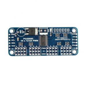
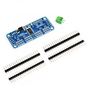
16-Channel 12-bit PWM/Servo Driver I2C interface PCA9685
- ₹522
- Operating voltage: 2.3V to 5.5V 5.5V tolerant inputs Can operate at minus 40 degrees Celsius to 85 degrees Celsius Software reset feature (SWRST Call) allows the device via I2C bus reset 25MHz internal oscillator requires no external components The maximum allowable 50MHz external clock input
-
-
-
-
- Out of StockRead more
- Brushed / Brushless DC motor Driver, Drivers, Motors, Pumps
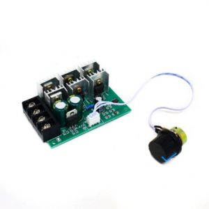
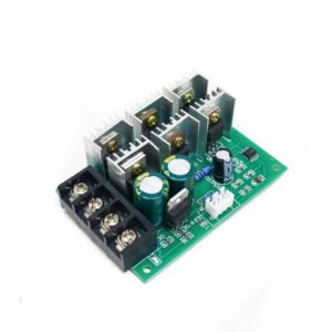
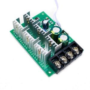
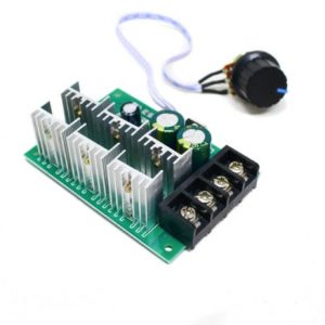
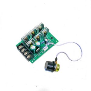
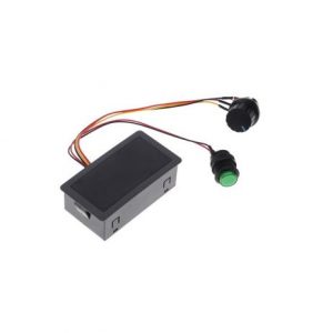
2000W PWM Motor Speed Controller With Potentiometer
- ₹648
- Maximum Power: 2000W Operating Voltage: 9-55 VDC Operating Current: 0-40 A Control Frequency: 25KHZ
-
-
-
-
-
-
-
- Out of StockRead more
- Drivers, Motors, Pumps, Stepper Motor Drivers
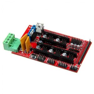
3D Printer Controller Board RAMPS 1.4 Arduino Mega Shield RepRap Prusa Model
- ₹325
- Supply Voltage: 12V Standard interfaces (as that of the extruder) Reserved GCI like I2C and RS232 3 MOSFET??s?are applied to the heater/ fan and thermistor circuit. Another 5A added to protect the component parts. An 11A fuse is added to the hotbed. Support 5 stepper drive board
-
-
-
- Out of StockRead more
- Cytron Motor Drivers, Drivers, Motors, Pumps
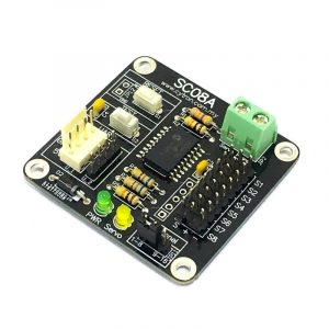
8 Channel Servo Controller SC08A
- ₹1,719
- Resolution: 8000 steps = 0.25us. UART: 9600 baud rate. Servo pulse range: 0.5ms to 2.5ms. Dimension :?48 x 46 x 14 (LxWxH) mm. 8 channels: Servo-driven independently. Extendable to 16 Channels: Two controllers linked together to drive 16 servos. Optional Position Reporting: User may request the position of an individual servo.
-
-
-
- Out of StockRead more
- Drivers, Motors, Pumps, Stepper Motor Drivers
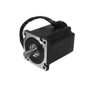
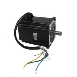
86BLS98-X015 48V-RPM3000-1.56N-m- 111.5mm
- ₹8,495
- Model: 86BLS98-X015 Operating voltage: 48V Shaft Type: Key Type Torque: 1.56?N-m
-
-
-
-
-
-
- Out of StockRead more
- Drivers, Motors, Pumps, Stepper Motor Drivers
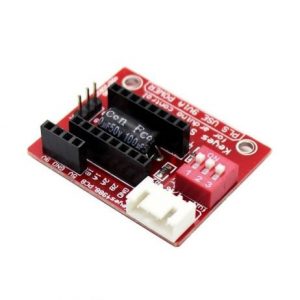
A4988 Stepper Motor Driver Controller Board- RED
- ₹74
- Compact size, easy to install and use. All jumpers hit the ON position to indicate 16 subdivisions (4988) or 32 subdivisions (8825). Jm connection motor: Jv Connects 5V and 12V-24V Power Supply. E /S /D /G of Jc corresponds to Enable /Step /Dir /Gnd driving signal output on the connection respectively.
-
-
-
- Out of StockRead more
- Cytron Motor Drivers, Drivers, Motors, Pumps
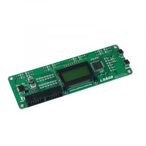
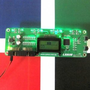
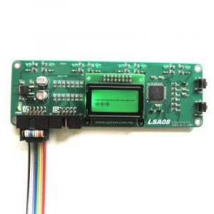
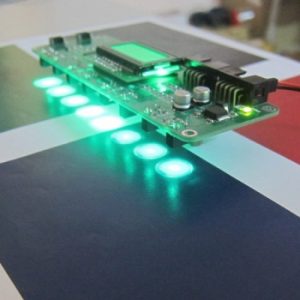
Advanced Auto-Calibrating Line Sensor LSA08
- ₹5,518
- 8 sensor pairs spaced 16mm. 12V input power Onboard Mode and a Select button for instant configuration of LSA08 LCD display unit showing 8 sensors analog value with bar chart and line position. Simple Auto-Calibration function to the line following surface. Low current consumption (typically 26mA) Works on glossy or reflective surface Refresh rate up to 200Hz.
-
-
-

-
-
-
-
- Out of StockRead more
- Drivers, Motors, Pumps, Stepper Motor Drivers
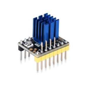
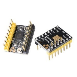
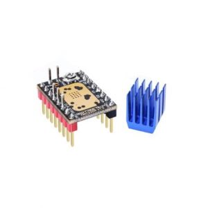
BIGTREETECH BTT TMC2130 V3.0 Stepper Motor Driver
- ₹884
- 1. Up to 256 subdivisions; 2. Support SPI interface control; 3. Do not lose step when driving under high load; 4. Logic voltage: 3.3V/5V; 5. Input voltage range: 12V/24V DC; 6. Motor operating current 1.2a (peak 2A) can be adjusted 7. Spreadcycle ensures that the stepper motor has a smooth transition without dead zone current when passing zero.
-
-
-
-
- Out of StockRead more
- Drivers, Motors, Pumps, Stepper Motor Drivers
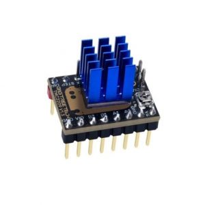
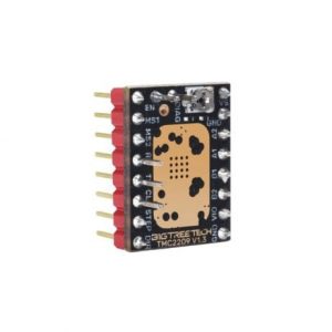
BIGTREETECH BTT TMC2209 V1.3 Stepper Motor Driver
- ₹628
- Silent Motor Movement Sensor less Homing Dynamic Current Control Supports UART, STEP/DIR Modes
-
-
-
-
-
-
- Out of StockRead more
- Drivers, Motors, Pumps, Stepper Motor Drivers
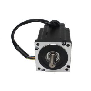
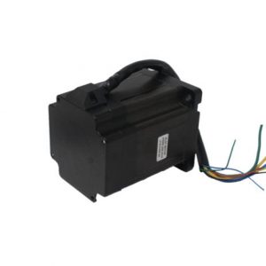
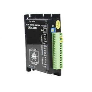
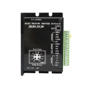
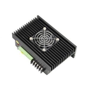
BLD120 Brushless DC Motor Driver
- ₹3,397
- Model: BLD120 Input voltage:+12 to +30V DC Rated (RPM): 0 to 20000
-
-
-
-
-
-
-
- Out of StockRead more
- Drivers, Motors, Pumps, Stepper Motor Drivers
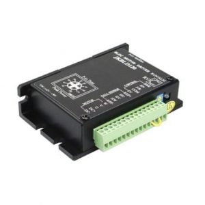
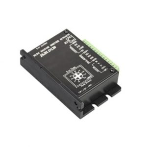
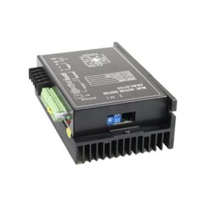
BLD750 Brushless DC Motor Driver
- ₹8,684
- Model: BLD750 Input voltage: 15~52 VDC Rated (RPM): 0-20000
-
-
-
-
-
-
-
- Out of StockRead more
- Brushed / Brushless DC motor Driver, Drivers, Motors, Pumps
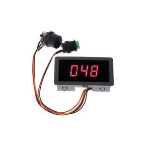
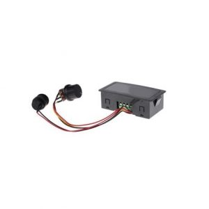
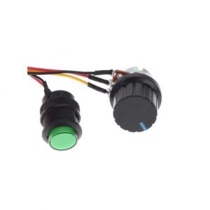
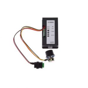
CCM5D Digital PWM DC Motor Speed Controller With Display Standard Quality
- ₹353
- Operating Voltage: 6-30 VDC Operating Current: up to 8A Material: ABS Frequency:16 Khz Dimension:80x40x25 mm
-
-
-
-
-
-
-
- Out of StockRead more
- Cytron Motor Drivers, Drivers, Motors, Pumps
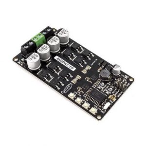
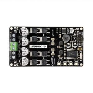
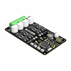
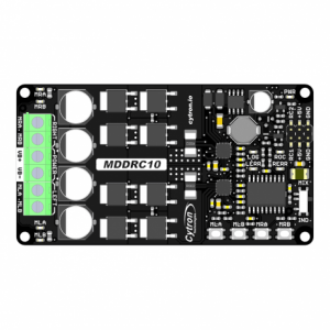
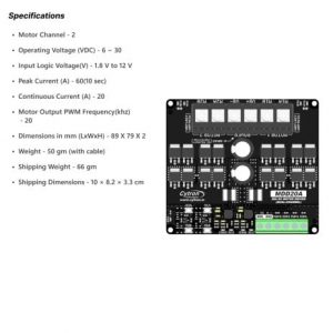
Cytron 10Amp 7V-30V DC Motor Driver for R/C (2 Channel) MDDRC10
- ₹3,893
- Operating Voltage: DC 7 V to 30 V Maximum Motor Current: 10 A continuous, 30 A peak Motor Output PWM Frequency: 20 kHz RC Input Voltage (RC1 & RC2): Low Level: 0-0.7 V | High Level: 1.5-15 V Output Maximum Current: 0-500 mA
-
-
-
-
-
-
- Out of StockRead more
- Cytron Motor Drivers, Drivers, Motors, Pumps
Cytron 20Amp 6V-30V DC Motor Driver (2 Channels)
- ₹3,503
- Operating Voltage: DC 6V to 30V. Inputs compatible with 1.8V, 3.3V, 5V, and 12V logic . PWM frequency up to 20kHz. Compatible with sign-magnitude and locked-antiphase PWM operation.
-
-
-
-
-
-
-
- Out of StockRead more
- Cytron Motor Drivers, Drivers, Motors, Pumps
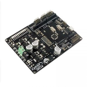
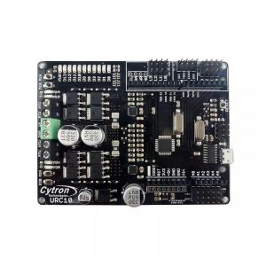
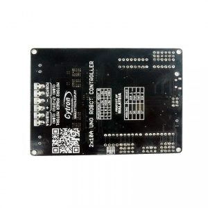
Cytron Dual channel 10A Motor Driver UNO Robot Controller
- ₹3,645
- Onboard 1A (maximum) 5V voltage regulator. Onboard 500mA (maximum) 3.3V voltage regulator. 0-5V digital outputs with 3.3V compatible inputs. 14 Digital I/O Pins (6 PWM outputs).(4 pin used for Motor driver) 6 Analog Inputs (Can be digital I/O too). Maximum current up to 10A continuous and 30A Peak. ISP 6-pin Header. 32k Flash Memory. 16MHz Clock Speed. R3 Shield Compatible.
-
-
-
-
-
- Out of StockRead more
- Cytron Motor Drivers, Drivers, Motors, Pumps
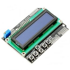
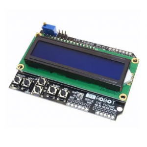
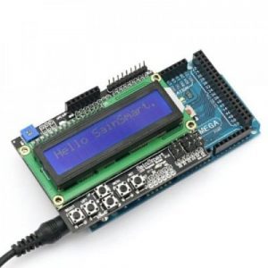
Cytron LCD keypad Shield High Quality
- ₹459
- Provides a user-friendly interface that allows users to go through the menu, make selections etc. It consists of a 1602 white character blue backlight LCD. The keypad consists of 6 keys select, up, right, down, left and reset. To save the digital IO pins, the keypad interface only uses one ADC channel. The key value is read out through a…
-
-
-
-
-
- Out of StockRead more
- Cytron Motor Drivers, Drivers, Motors, Pumps
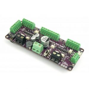
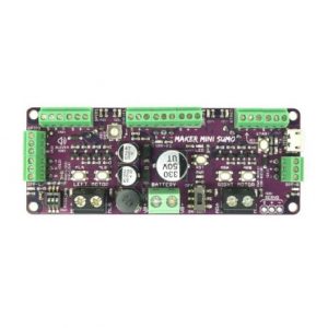
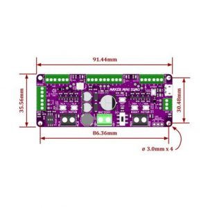
Cytron Maker Mini Sumo Controller: Simplifying Sumo Robot for Beginner
- ₹2,205
- Arduino Uno/Nano Compatible Powerful Motor Driver (2 Channels) Reversed Polarity Protection Solderless Connection Shock Proof On/Off Switch Support RC mode Easy Troubleshooting
-
-
-
-
-
- Out of StockRead more
- Cytron Motor Drivers, Drivers, Motors, Pumps
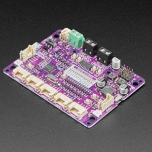
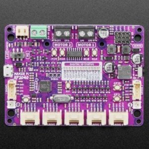
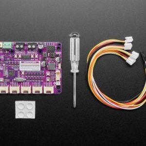
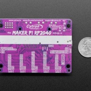
Cytron Maker Pi RP2040 : Simplifying Robotics with Raspberry Pi RP2040
- ₹1,179
- RP2040 SoC ARM Cortex M0+ running up to 133Mhz SRAM 264kB Flash Storage 2MB of QSPI LiPo / Li-ion battery charging USB Port Micro USB
-
-
-
-
-
-
- Out of StockRead more
- Cytron Motor Drivers, Drivers, Motors, Pumps
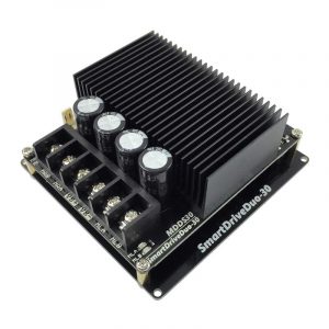
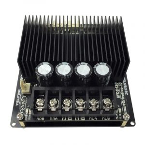
Cytron Smart Drive Mdds30 Dual 30A (80A Peak)
- ₹7,735
- Battery low voltage indicator. Battery over voltage indicator. Thermal protection. Current limit protection. Bi-directional control for dual brushed DC motor. Support motor voltage from?7V to 35VDC. Dimension: 103 x 97 x 40 (LxWxH) mm.
-
-
-
-
-
-
-
- Out of StockRead more
- Brushed / Brushless DC motor Driver, Drivers, Motors, Pumps
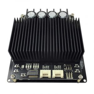
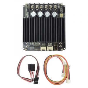
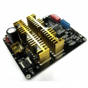
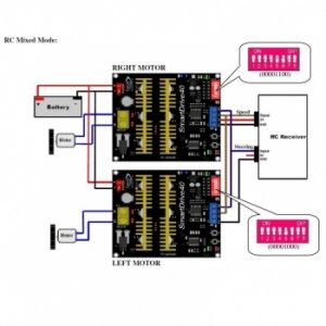
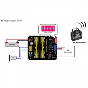
Cytron Smartdrive40 40Amp Dc Motor Driver (Peak 80Amp) Mds40A
- ₹6,182
- Bi-directional control for a single brushed DC motor. Support motor from 7V to 25V. Maximum current up to 80A peak (1 second), 40A (5 minutes) or 30A (> 20 minutes) continuously. 16 KHz switching frequency for quiet operation. Reverse polarity protection. LiPo battery low voltage warning. Thermal protection. Current limiting base on temperature.
-
-

-
-
-
-
-
- Out of StockRead more
- Cytron Motor Drivers, Drivers, Motors, Pumps
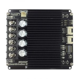
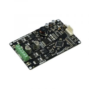
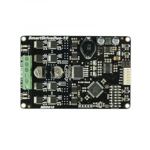
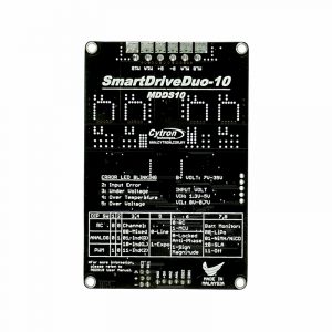
Cytron SmartDriveDuo-10 MDDS10 DC MOTOR DRIVER
- ₹5,623
- Single power operation Dual Channels means it can drive two brush motor independently, or mixed. Support Signed magnitude and Locked Anti-phase in PWM mode. Two manual/test buttons for each channel. Two output indicator LEDs for each channel. Power, Error indicator, RUN status (Left and Right) LEDs On board reset button to restart the MCU after changing operation mode. Operating modes:…
-
-
-
-
-
- Out of StockRead more
- Brushed / Brushless DC motor Driver, Drivers, Motors, Pumps
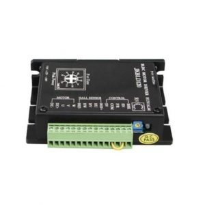
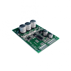
DC15V-36V-15A 500W Brushless Motor Controller Hall Motor Balanced Car Driver Board with Hall Drive
- ₹1,555
- Voltage range: 15V-36V Peak current: 20A PWM speed control: PWM frequency 1-20KHZ Duty cycle: 0-100% Drive power: ?? 500W
-
-
-
-
- Out of StockRead more
- Brushed / Brushless DC motor Driver, Drivers, Motors, Pumps
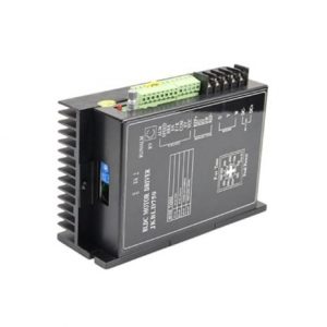
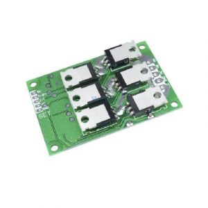
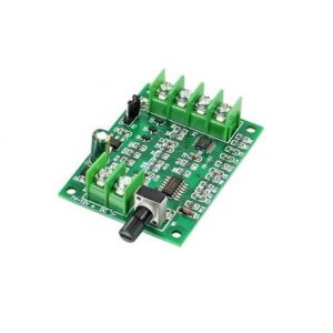
DC7V-12V Brushless Motor Driver Controller Board For Hard Drive Motor 3/4 Wire
- ₹576
- Driver voltage: DC7-12V Working voltage: ??1.2A Speed adjust:0%-100% Color: Green and Black
-
-
-
- Out of StockRead more
- Drivers, Motors, Pumps, Stepper Motor Drivers
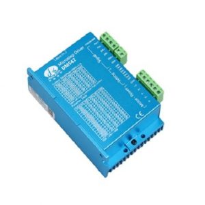
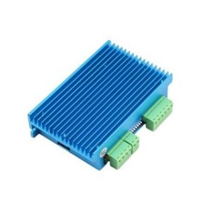
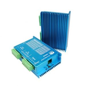
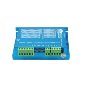
DM542 Stepper Motor Driver
- ₹2,804
- Model: DM542 Power Consumption: 80 Watt Input Current:
-
-
-
-
-
-