-
- Out of StockRead more
- Drivers, Motors, Pumps, Servo Motor Drivers
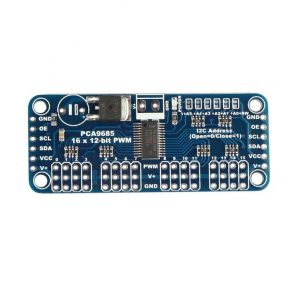
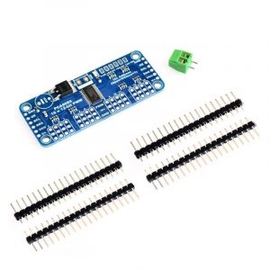
16-Channel 12-bit PWM/Servo Driver I2C interface PCA9685
- ₹522
- Operating voltage: 2.3V to 5.5V 5.5V tolerant inputs Can operate at minus 40 degrees Celsius to 85 degrees Celsius Software reset feature (SWRST Call) allows the device via I2C bus reset 25MHz internal oscillator requires no external components The maximum allowable 50MHz external clock input
-
-
-
-
- Out of StockRead more
- Brushed / Brushless DC motor Driver, Drivers, Motors, Pumps
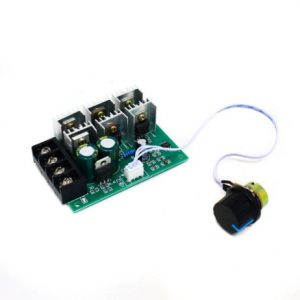
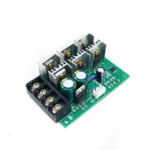
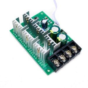
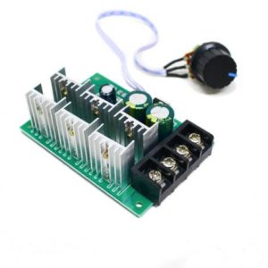
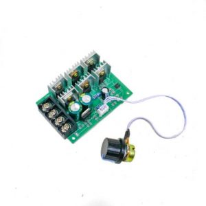
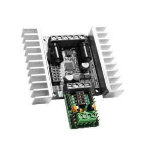
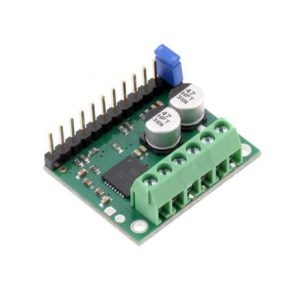
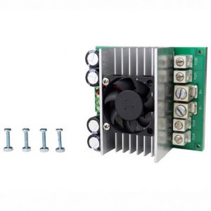
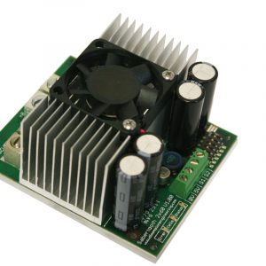
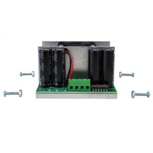
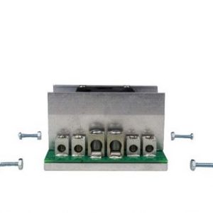
2000W PWM Motor Speed Controller With Potentiometer
- ₹648
- Maximum Power: 2000W Operating Voltage: 9-55 VDC Operating Current: 0-40 A Control Frequency: 25KHZ
-
-
-
-
-
-
-
- Out of StockRead more
- Drivers, Motors, Pumps, Stepper Motor Drivers
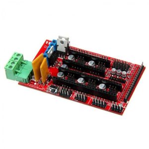
3D Printer Controller Board RAMPS 1.4 Arduino Mega Shield RepRap Prusa Model
- ₹325
- Supply Voltage: 12V Standard interfaces (as that of the extruder) Reserved GCI like I2C and RS232 3 MOSFET??s?are applied to the heater/ fan and thermistor circuit. Another 5A added to protect the component parts. An 11A fuse is added to the hotbed. Support 5 stepper drive board
-
-
-
- Out of StockRead more
- Cytron Motor Drivers, Drivers, Motors, Pumps
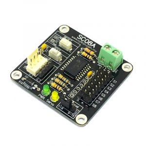
8 Channel Servo Controller SC08A
- ₹1,719
- Resolution: 8000 steps = 0.25us. UART: 9600 baud rate. Servo pulse range: 0.5ms to 2.5ms. Dimension :?48 x 46 x 14 (LxWxH) mm. 8 channels: Servo-driven independently. Extendable to 16 Channels: Two controllers linked together to drive 16 servos. Optional Position Reporting: User may request the position of an individual servo.
-
-
-
- Out of StockRead more
- Drivers, Motors, Pumps, Stepper Motor Drivers
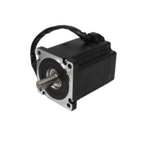
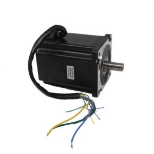
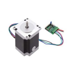
86BLS98-X015 48V-RPM3000-1.56N-m- 111.5mm
- ₹8,495
- Model: 86BLS98-X015 Operating voltage: 48V Shaft Type: Key Type Torque: 1.56?N-m
-
-
-
-
-
-
- Out of StockRead more
- Drivers, Motors, Pumps, Stepper Motor Drivers
A4988 Stepper Motor Driver Controller Board- RED
- ₹74
- Compact size, easy to install and use. All jumpers hit the ON position to indicate 16 subdivisions (4988) or 32 subdivisions (8825). Jm connection motor: Jv Connects 5V and 12V-24V Power Supply. E /S /D /G of Jc corresponds to Enable /Step /Dir /Gnd driving signal output on the connection respectively.
-
-
-
- Out of StockRead more
- Cytron Motor Drivers, Drivers, Motors, Pumps
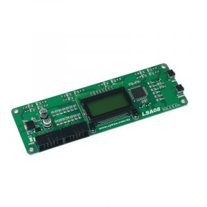
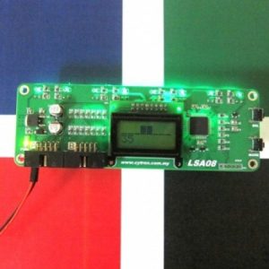
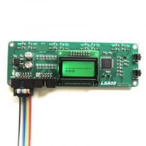
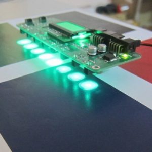
Advanced Auto-Calibrating Line Sensor LSA08
- ₹5,518
- 8 sensor pairs spaced 16mm. 12V input power Onboard Mode and a Select button for instant configuration of LSA08 LCD display unit showing 8 sensors analog value with bar chart and line position. Simple Auto-Calibration function to the line following surface. Low current consumption (typically 26mA) Works on glossy or reflective surface Refresh rate up to 200Hz.
-
-
-

-
-
-
-
- Out of StockRead more
- Drivers, Motors, Pumps, Stepper Motor Drivers
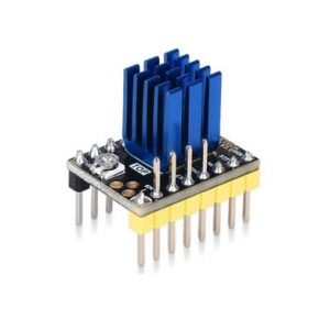
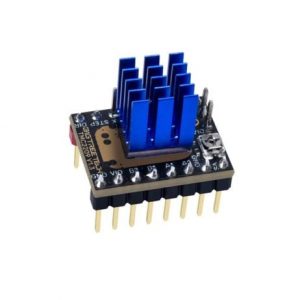
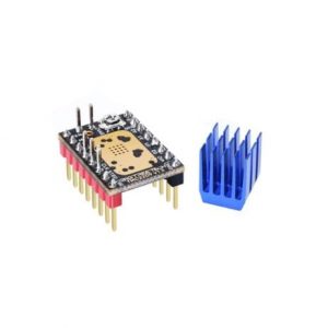
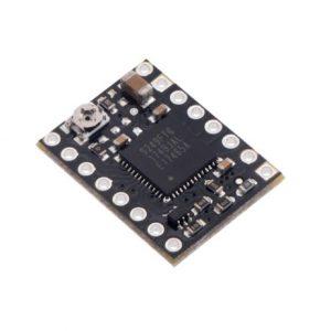
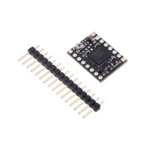
BIGTREETECH BTT TMC2130 V3.0 Stepper Motor Driver
- ₹884
- 1. Up to 256 subdivisions; 2. Support SPI interface control; 3. Do not lose step when driving under high load; 4. Logic voltage: 3.3V/5V; 5. Input voltage range: 12V/24V DC; 6. Motor operating current 1.2a (peak 2A) can be adjusted 7. Spreadcycle ensures that the stepper motor has a smooth transition without dead zone current when passing zero.
-
-
-
-
- Out of StockRead more
- Drivers, Motors, Pumps, Stepper Motor Drivers
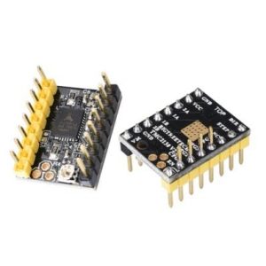
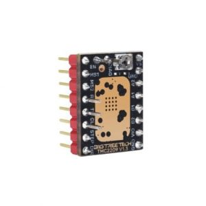
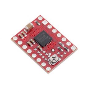
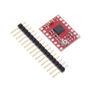
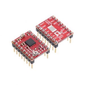
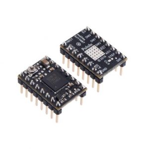
BIGTREETECH BTT TMC2209 V1.3 Stepper Motor Driver
- ₹628
- Silent Motor Movement Sensor less Homing Dynamic Current Control Supports UART, STEP/DIR Modes
-
-
-
-
-
-
- Out of StockRead more
- Drivers, Motors, Pumps, Stepper Motor Drivers
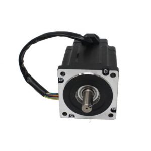
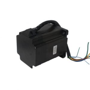
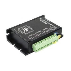
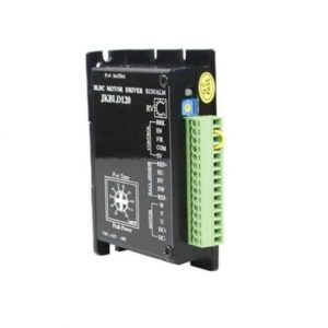
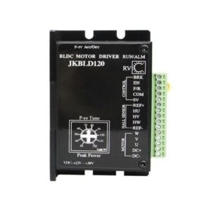
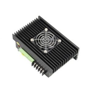
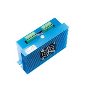
BLD120 Brushless DC Motor Driver
- ₹3,397
- Model: BLD120 Input voltage:+12 to +30V DC Rated (RPM): 0 to 20000
-
-
-
-
-
-
-
- Out of StockRead more
- Drivers, Motors, Pumps, Stepper Motor Drivers
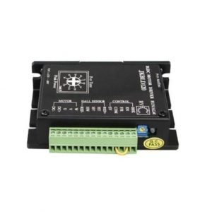
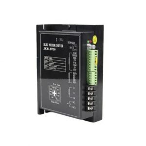
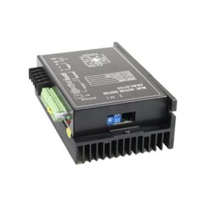
BLD750 Brushless DC Motor Driver
- ₹8,684
- Model: BLD750 Input voltage: 15~52 VDC Rated (RPM): 0-20000
-
-
-
-
-
-
-
- Out of StockRead more
- Brushed / Brushless DC motor Driver, Drivers, Motors, Pumps
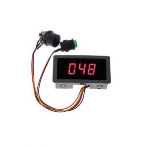
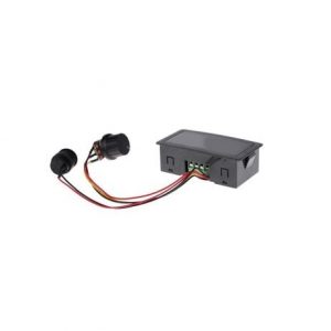
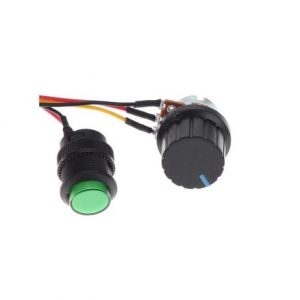
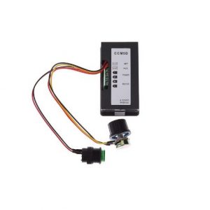
CCM5D Digital PWM DC Motor Speed Controller With Display Standard Quality
- ₹353
- Operating Voltage: 6-30 VDC Operating Current: up to 8A Material: ABS Frequency:16 Khz Dimension:80x40x25 mm
-
-
-
-
-
-
-
- Out of StockRead more
- Cytron Motor Drivers, Drivers, Motors, Pumps
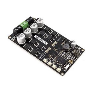
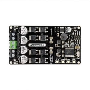
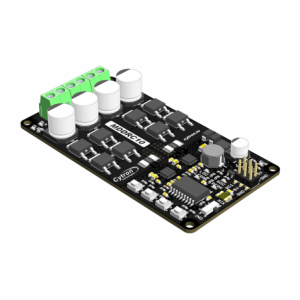
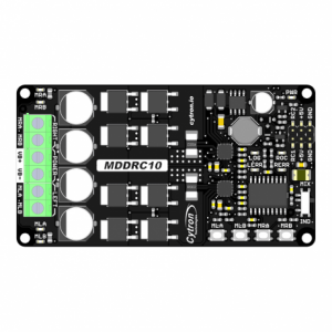
Cytron 10Amp 7V-30V DC Motor Driver for R/C (2 Channel) MDDRC10
- ₹3,893
- Operating Voltage: DC 7 V to 30 V Maximum Motor Current: 10 A continuous, 30 A peak Motor Output PWM Frequency: 20 kHz RC Input Voltage (RC1 & RC2): Low Level: 0-0.7 V | High Level: 1.5-15 V Output Maximum Current: 0-500 mA
-
-
-
-
-
-
- Out of StockRead more
- Cytron Motor Drivers, Drivers, Motors, Pumps
Cytron 20Amp 6V-30V DC Motor Driver (2 Channels)
- ₹3,503
- Operating Voltage: DC 6V to 30V. Inputs compatible with 1.8V, 3.3V, 5V, and 12V logic . PWM frequency up to 20kHz. Compatible with sign-magnitude and locked-antiphase PWM operation.
-
-
-
-
-
-
-
- Out of StockRead more
- Cytron Motor Drivers, Drivers, Motors, Pumps
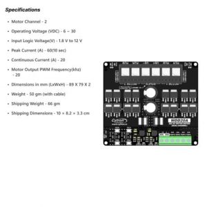
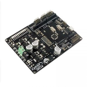
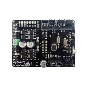
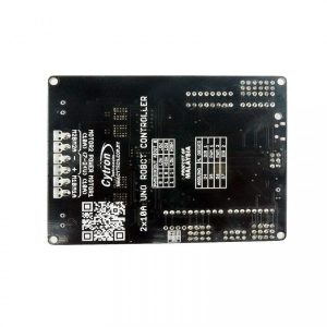
Cytron Dual channel 10A Motor Driver UNO Robot Controller
- ₹3,645
- Onboard 1A (maximum) 5V voltage regulator. Onboard 500mA (maximum) 3.3V voltage regulator. 0-5V digital outputs with 3.3V compatible inputs. 14 Digital I/O Pins (6 PWM outputs).(4 pin used for Motor driver) 6 Analog Inputs (Can be digital I/O too). Maximum current up to 10A continuous and 30A Peak. ISP 6-pin Header. 32k Flash Memory. 16MHz Clock Speed. R3 Shield Compatible.
-
-
-
-
-
- Out of StockRead more
- Cytron Motor Drivers, Drivers, Motors, Pumps
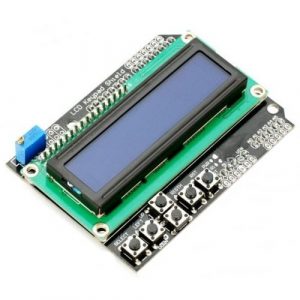
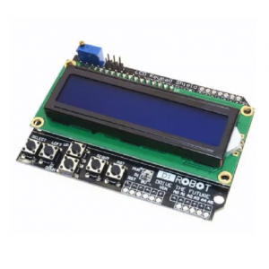
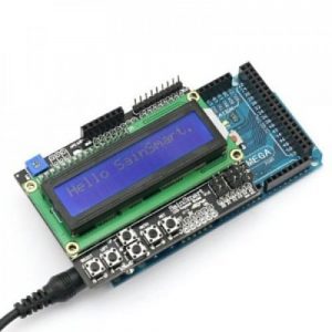
Cytron LCD keypad Shield High Quality
- ₹459
- Provides a user-friendly interface that allows users to go through the menu, make selections etc. It consists of a 1602 white character blue backlight LCD. The keypad consists of 6 keys select, up, right, down, left and reset. To save the digital IO pins, the keypad interface only uses one ADC channel. The key value is read out through a…
-
-
-
-
-
- Out of StockRead more
- Cytron Motor Drivers, Drivers, Motors, Pumps
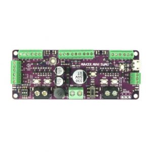
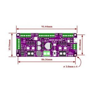
Cytron Maker Mini Sumo Controller: Simplifying Sumo Robot for Beginner
- ₹2,205
- Arduino Uno/Nano Compatible Powerful Motor Driver (2 Channels) Reversed Polarity Protection Solderless Connection Shock Proof On/Off Switch Support RC mode Easy Troubleshooting
-
-
-
-
-
- Out of StockRead more
- Cytron Motor Drivers, Drivers, Motors, Pumps
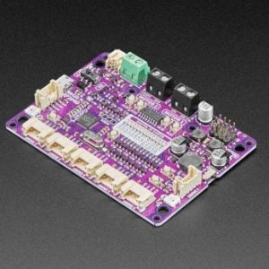
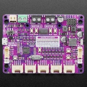
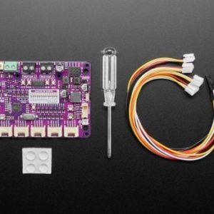
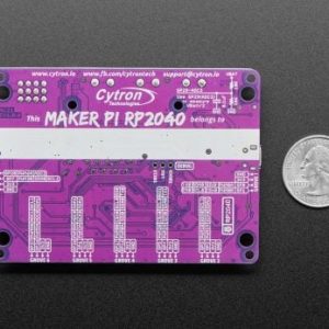
Cytron Maker Pi RP2040 : Simplifying Robotics with Raspberry Pi RP2040
- ₹1,179
- RP2040 SoC ARM Cortex M0+ running up to 133Mhz SRAM 264kB Flash Storage 2MB of QSPI LiPo / Li-ion battery charging USB Port Micro USB
-
-
-
-
-
-
- Out of StockRead more
- Cytron Motor Drivers, Drivers, Motors, Pumps
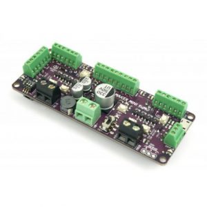
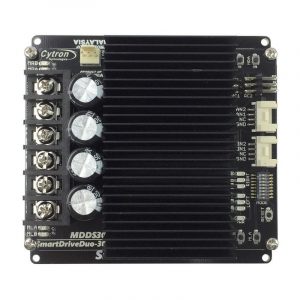
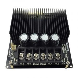
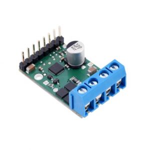
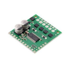
Cytron Smart Drive Mdds30 Dual 30A (80A Peak)
- ₹7,735
- Battery low voltage indicator. Battery over voltage indicator. Thermal protection. Current limit protection. Bi-directional control for dual brushed DC motor. Support motor voltage from?7V to 35VDC. Dimension: 103 x 97 x 40 (LxWxH) mm.
-
-
-
-
-
-
-
- Out of StockRead more
- Brushed / Brushless DC motor Driver, Drivers, Motors, Pumps
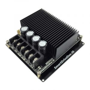
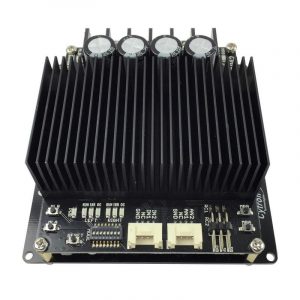
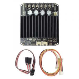
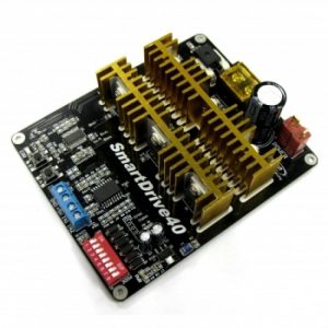
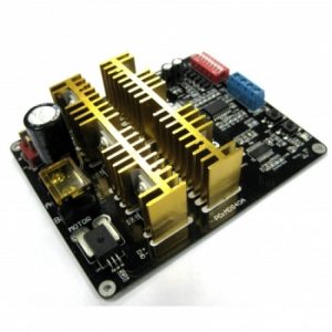
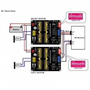
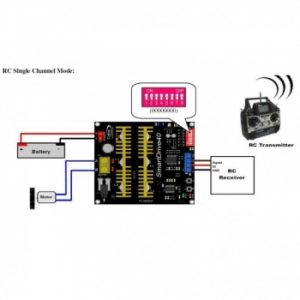
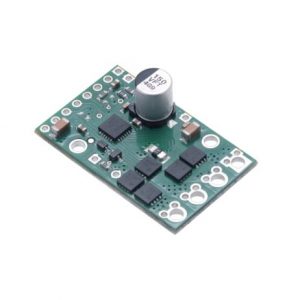
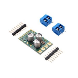
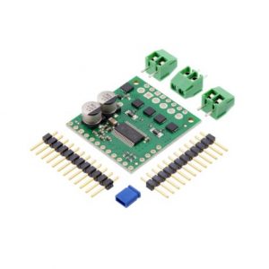
Cytron Smartdrive40 40Amp Dc Motor Driver (Peak 80Amp) Mds40A
- ₹6,182
- Bi-directional control for a single brushed DC motor. Support motor from 7V to 25V. Maximum current up to 80A peak (1 second), 40A (5 minutes) or 30A (> 20 minutes) continuously. 16 KHz switching frequency for quiet operation. Reverse polarity protection. LiPo battery low voltage warning. Thermal protection. Current limiting base on temperature.
-
-

-
-
-
-
-
- Out of StockRead more
- Cytron Motor Drivers, Drivers, Motors, Pumps
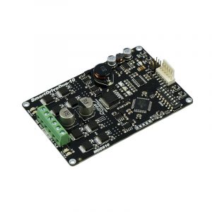
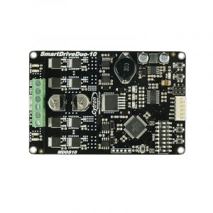
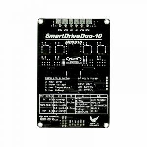
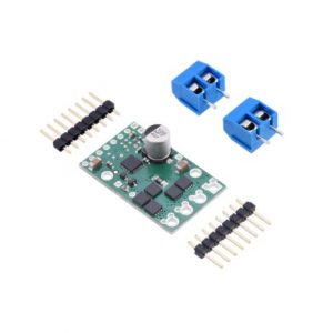
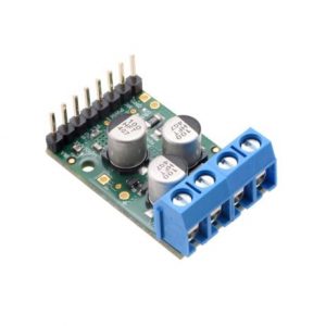
Cytron SmartDriveDuo-10 MDDS10 DC MOTOR DRIVER
- ₹5,623
- Single power operation Dual Channels means it can drive two brush motor independently, or mixed. Support Signed magnitude and Locked Anti-phase in PWM mode. Two manual/test buttons for each channel. Two output indicator LEDs for each channel. Power, Error indicator, RUN status (Left and Right) LEDs On board reset button to restart the MCU after changing operation mode. Operating modes:…
-
-
-
-
-
- Out of StockRead more
- Brushed / Brushless DC motor Driver, Drivers, Motors, Pumps
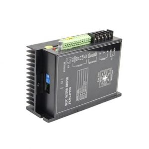
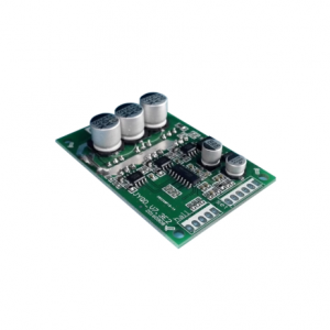
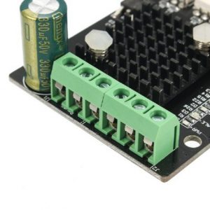
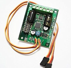
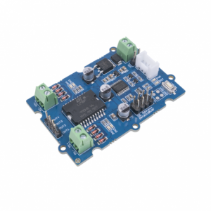
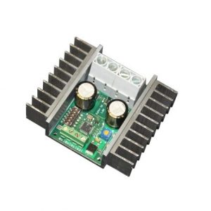
DC15V-36V-15A 500W Brushless Motor Controller Hall Motor Balanced Car Driver Board with Hall Drive
- ₹1,555
- Voltage range: 15V-36V Peak current: 20A PWM speed control: PWM frequency 1-20KHZ Duty cycle: 0-100% Drive power: ?? 500W
-
-
-
-
- Out of StockRead more
- Brushed / Brushless DC motor Driver, Drivers, Motors, Pumps
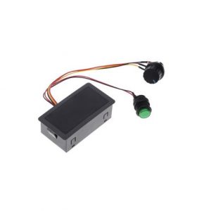
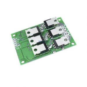
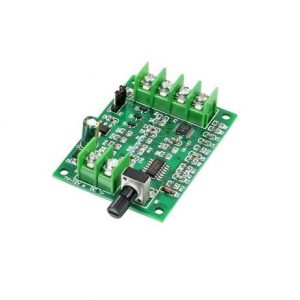
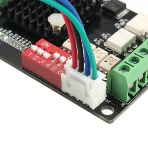
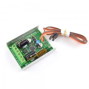
DC7V-12V Brushless Motor Driver Controller Board For Hard Drive Motor 3/4 Wire
- ₹576
- Driver voltage: DC7-12V Working voltage: ??1.2A Speed adjust:0%-100% Color: Green and Black
-
-
-
- Out of StockRead more
- Drivers, Motors, Pumps, Stepper Motor Drivers
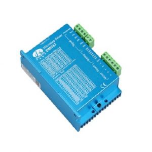
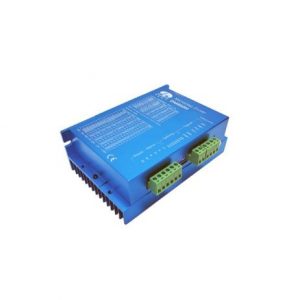
DM542 Stepper Motor Driver
- ₹2,804
- Model: DM542 Power Consumption: 80 Watt Input Current:
-
-
-
-
-
-
-
- Out of StockRead more
- Drivers, Motors, Pumps, Stepper Motor Drivers
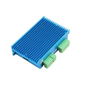
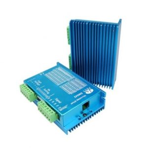
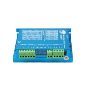
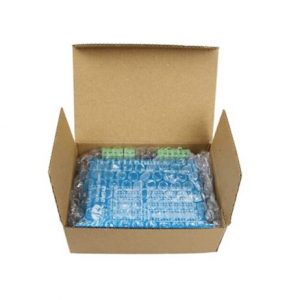
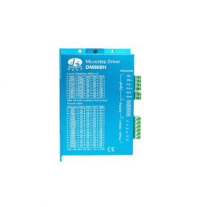
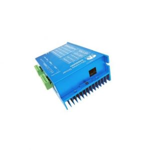
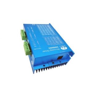
DM860H Stepper Motor Driver
- ₹4,455
- Model: DM860H Input voltage: 24V??110VDC Weight: 487g Input Frequency: up to 200KHz
-
-
-
-
-
-
-
- Out of StockRead more
- Dimension Engineering Motor Drivers, Drivers, Motors, Pumps
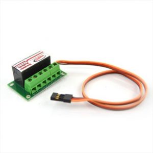
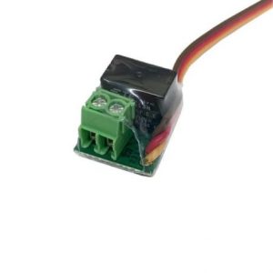
Double Switch radio controlled dual 8A relay
- ₹2,985
- Product: Relay Max relay voltage: 240VAC Max relay current: 8A at 12VDC, 8A at 240VAC Relay resistance: 100 mΩ max Operating voltage: 3.5V to 5.5V
-
-
-
- Out of StockRead more
- Drivers, Motors, Pumps, Stepper Motor Drivers
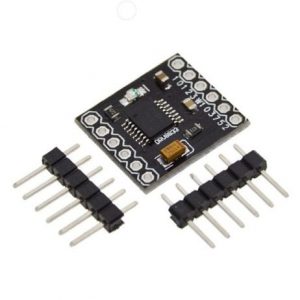
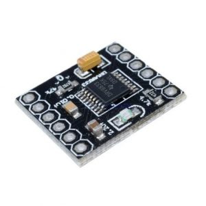
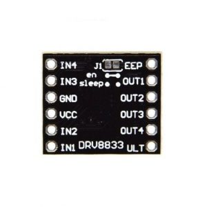
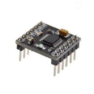
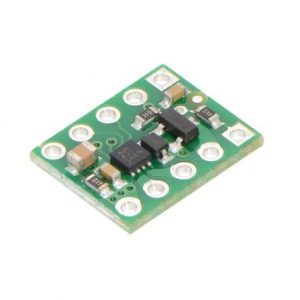
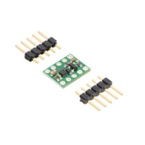
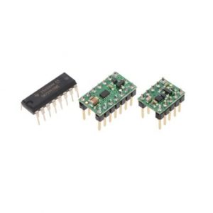
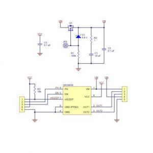
DRV8833 2 Channel DC Motor Driver
- ₹77
- Dual-H-bridge motor driver: can drive two DC motors or one bipolar stepper motor Operating voltage: 2.7?????V to 10.8?V Output current: 1.2?A continuous (2?A peak) per motor Inputs are 3V- and 5V-compatible
-
-
-
-
-
-
- Out of StockRead more
- Brushed / Brushless DC motor Driver, Drivers, Motors, Pumps
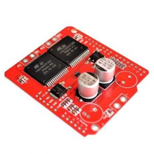
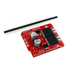
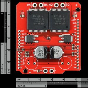
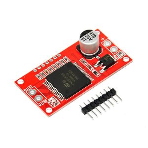
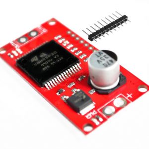
Dual Monster Moto Shield VNH3ASP30 DC Motor Driver 2x14A (Peak 30A)
- ₹3,933
- Voltage Max: 16V Maximum current rating: 30 A Practical Continuous Current: 14 A Current sensing available to Arduino analog pin MOSFET on-resistance: 19 mΩ (per leg) Maximum PWM frequency: 20 kHz Thermal Shutdown Undervoltage and Overvoltage shutdown.
-
-
-
-
-
-
- Out of StockRead more
- Drivers, Motors, Pumps, Servo Motor Drivers
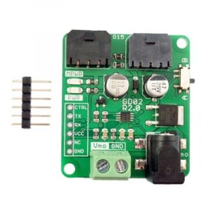
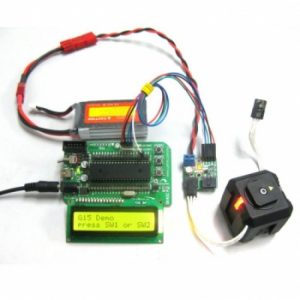
G15 Driver for G15 Cube Servo
- ₹578
- Maximum Continuous Current: 8A 2 x G15 Cube Servo ports (can be daisy chained to more servos) External power terminal for Cube Servo. 2 LEDs as logic power and servo power indicators. 3.3V and 5V signals compatible.
-
-
-
-
- Out of StockRead more
- Dimension Engineering Motor Drivers, Drivers, Motors, Pumps
Kangaroo X2 Motion Controller
- ₹2,217
- Model: Kangaroo x2 2 channel self-tuning PID controller Position or speed control Quadrature encoder feedback or potentiometer feedback Support for limit switches and mechanical stops Analog, R/C, and serial inputs
-
-
-
-
-
- Out of StockRead more
- Brushed / Brushless DC motor Driver, Drivers, Motors, Pumps
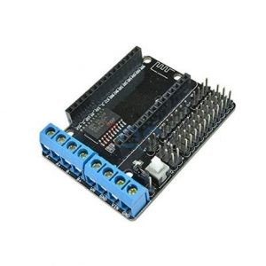
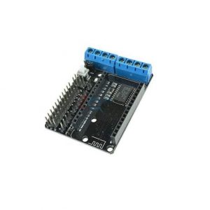
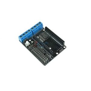
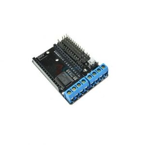
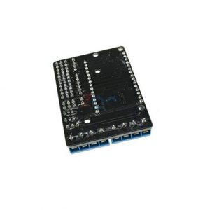
L293D Motor Driver Board for ESP8266 WiFi NodeMcu Lua ESP12E
- ₹150
- Motor Power Range: 4.5V ~ 36V Control supply range: 4.5V ~ 9V Logical operating current Iss: ??60mA Driving part of the work current Io: ??1.2A Maximum power dissipation: 4W (T = 90 ??) Operating temperature : -25 ?? ~ + 125 ?? Drive Type: Dual high-power H-bridge driver
-
-
-
-
-
-
-
- Out of StockRead more
- Drivers, Motors, Pumps, Servo Motor Drivers
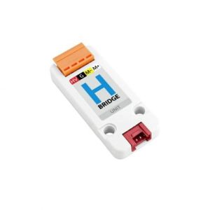
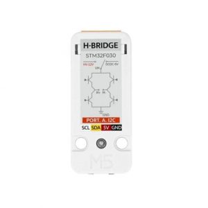
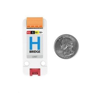
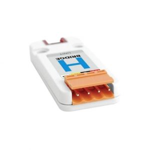
M5STACK H-bridge Unit(STM32F030)
- ₹1,250
- MCU: STM32F030F4P6 DC bidirectional motor driver chip RZ7899 External access DC voltage MAX: 12V I2C mailing address Default 0x20 (can be modified by toggle of the encoding switch) Maximum allowable current: 3A
-
-
-
-
-
-
-
- Out of StockRead more
- Drivers, Motors, Pumps, Stepper Motor Drivers
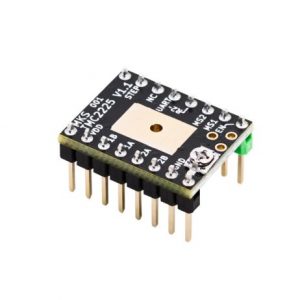
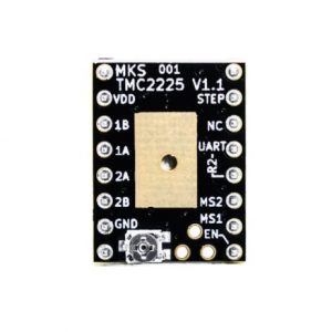
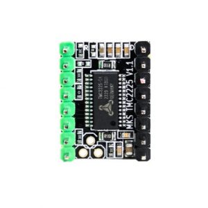
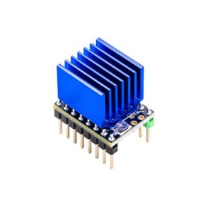
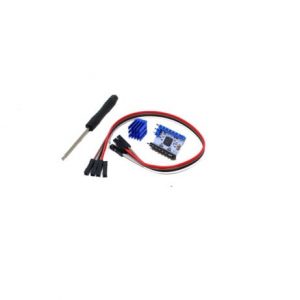
MakerBase MKS TMC2225 Stepper Motor Driver with Heat Sink
- ₹388
- MakerBase MKS TMC2225 Stepper Motor Driver with Heat Sink Model: TMC2225 Length: 20mm Width: 15mm Weight: 6g
-
-
-
-
-
-
- Out of StockRead more
- Cytron Motor Drivers, Drivers, Motors, Pumps
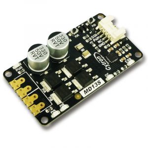
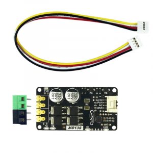
MD13S 13Amp DC Motor Driver GROVE Compatible
- ₹1,505
- Support motor voltage ranges from? 6V to 30V Maximum current up to 13A continuous and 30A peak (10 seconds). GROVE compatible 3.3V and 5V logic level input. SMD compatible Peak Current (A): 30 (10 seconds) Continuous Current (A): 1 No. of Channels: 1
-
-
-
-
- Out of StockRead more
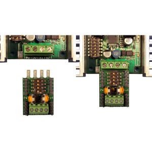
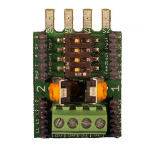
- Drivers, Motors, Pumps, Stepper Motor Drivers
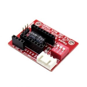
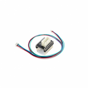
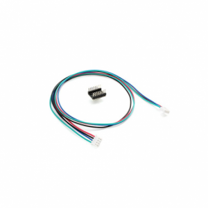
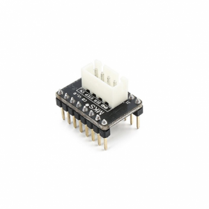
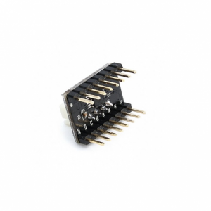
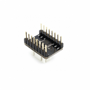
MKS CD V1.0 External Stepper Driver Interfacing Module
- ₹199
- Helps You Utilize External Stepper Drivers Acts As Interface Between Full-Sized Drivers And The A4988 Form Factor Easy To Use
-
-
-
-
-
-
-
- Out of StockRead more
- Drivers, Motors, Pumps, Stepper Motor Drivers
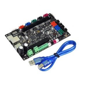
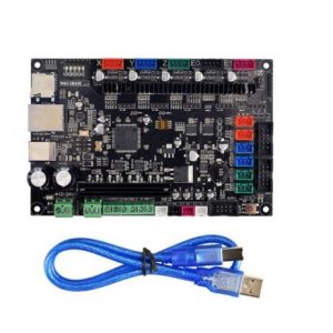
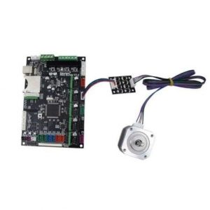
MKS SBASE V1.3 32-bit Open Source Smoothieboard
- ₹6,432
- 32bit 100M Cortex-M3 MCU-LPC 1768 High-performance Support highly modular open source firmware Smoothieware Easy for secondary development ?Support network function, then proceed remote control via IE Explorer.
-
-
-
-
-
- Out of StockRead more
- Drivers, Motors, Pumps, Stepper Motor Drivers
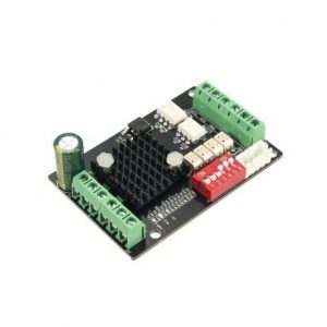
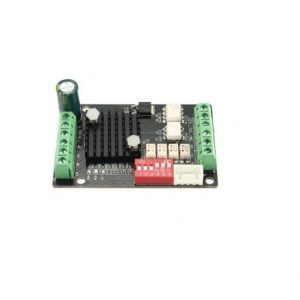
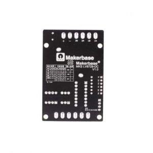
MKS-LV8729-OC 1.5A Ultra Quiet Stepper Motor Driver for 3D Printers and CNC
- ₹964
- High-speed optocoupler, high-speed without losing a step LV8729 chip, with over-current protection circuit, the maximum support 128 segments Automatic half-flow function A variety of input methods to meet a variety of interface needs The use of increased heat sink, good heat dissipation
-
-
-
-
-
-
-
- Out of StockRead more
- Brushed / Brushless DC motor Driver, Drivers, Motors, Pumps
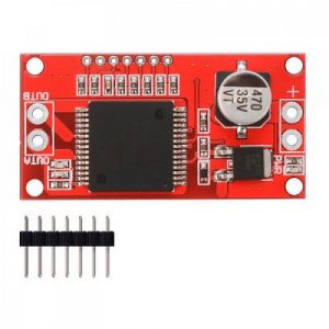
Monster Moto Shield VNH2SP30 Motor Driver 14A (Peak 30A)
- ₹2,477
- Voltage Max: 16V Maximum current rating: 30 A Practical Continuous Current: 14 A Current sensing available to Arduino analog pin MOSFET on-resistance: 34 mΩ Maximum PWM frequency: 10 kHz Thermal Shutdown Undervoltage and Overvoltage shutdown.
-
-
-
-
-
- Out of StockRead more
- Brushed / Brushless DC motor Driver, Drivers, Motors, Pumps
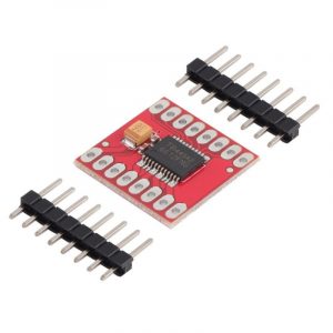
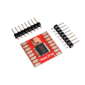
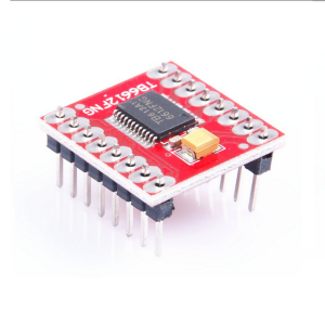
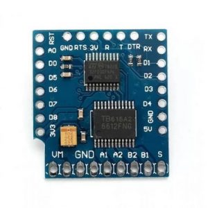
Motor Driver TB6612FNG Module Performance Ultra Small Volume 3 PI Matching Performance Ultra L298N
- ₹263
- CW/CCW/short break/stop motor control modes Built-in thermal shutdown circuit and a low voltage detecting circuit Standby control to save power CW/CCW/short brake/stop motor control modes Operating Voltage(VDC): 15 Peak Current (A): 3.2 Continuous Current (A): 1.2 No. of Channels: 1
-
-
-
-
-
- Out of StockRead more
- Dimension Engineering Motor Drivers, Drivers, Motors, Pumps
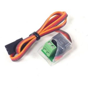
PicoSwitch radio controlled relay
- ₹2,089
- Product: Radio controlled relay Max relay voltage: 60VDC, 125VAC Max relay current: 1A at 24VDC, 0.5A at 125VAC (60W light-bulb) Relay resistance: 100 mO max Operating voltage: 3.5V to 5.5V
-
-
-
-
- Out of StockRead more
- Drivers, Motors, Pololu Motor Drivers, Pumps
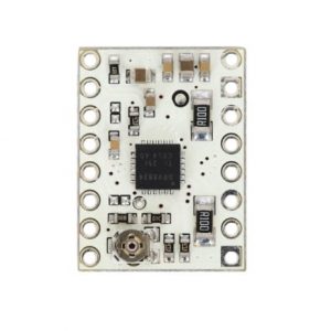
Pololu AMIS-30543 Stepper Motor Driver Carrier
- ₹2,359
- Compatible with 5?V and 3.3?V microcontrollers Integrated 5V regulator that can be used to supply an external microcontroller Integrated watchdog function Open coil detection Thermal warning indicates when the driver is close to the thermal shutdown temperature Over-current status and shutdown (short-to-ground and shorted-load protection) Reverse voltage protection
-
-
-
-
-
- Out of StockRead more
- Drivers, Motors, Pololu Motor Drivers, Pumps
Pololu BD65496MUV Single Brushed DC Motor Driver Carrier
- ₹1,630
- Under-voltage lockout on the logic supply and protection against over-temperature Carrier board adds reverse-voltage protection on the motor supply Compact size (0.6??×0.6??) Built-in under-voltage and over-temperature protection
-
-
-
-
- Out of StockRead more
- Drivers, Motors, Pololu Motor Drivers, Pumps
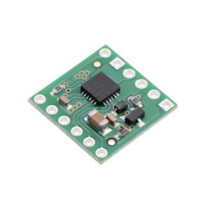
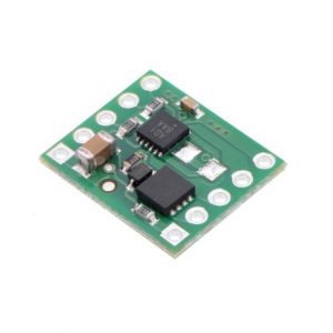
Pololu DRV8256E Single Brushed DC Motor Driver Carrier
- ₹1,863
- built-in protection against reverse-voltage, under-voltage, over-current, and over-temperature simple two-pin speed direction interface Under-voltage lockout and protection against over-current and over-temperature Simple interface requires only two I/O lines (one for direction and another for speed)
-
-
-
-
- Out of StockRead more
- Drivers, Motors, Pololu Motor Drivers, Pumps
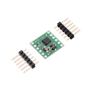
Pololu DRV8834 Low-Voltage Stepper Motor Driver Carrier
- ₹1,122
- Built-in regulator (no external logic voltage supply needed) Short-to-ground, short-to-supply, and shorted-load protection 4-layer, 2?oz copper PCB for improved heat dissipation Exposed solderable ground pad below the driver IC on the bottom of the PCB Simple step and direction control interface
-
-
-
-
-
- Out of StockRead more
- Drivers, Motors, Pololu Motor Drivers, Pumps
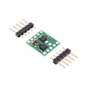
Pololu DRV8838 Single Brushed DC Motor Driver Carrier
- ₹897
- Reverse-voltage protection on the motor supply H-bridge motor driver: can drive one DC motor Motor supply voltage: 0?V to 11?V Logic supply voltage: 1.8?V to 7?V easy to use with standard solderless breadboards
-
-
-
-
-
-
- Out of StockRead more
- Drivers, Motors, Pololu Motor Drivers, Pumps
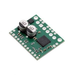
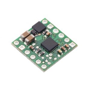
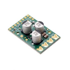
Pololu G2 High-Power Motor Driver 18v17
- ₹5,069
- Reverse-voltage protection Short circuit protection Current sensing and current limiting functionality Inputs compatible with 1.8?V, 3.3?V, and 5?V logic
-
-
-
-
-
- Out of StockRead more
- Drivers, Motors, Pololu Motor Drivers, Pumps
Pololu G2 High-Power Motor Driver 18v25
- ₹6,761
- Reverse-voltage protection Under voltage shutdown Short circuit protection Inputs compatible with 1.8?V, 3.3?V, and 5?V logic
-
-
-
-
-
- Out of StockRead more
- Drivers, Motors, Pololu Motor Drivers, Pumps
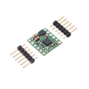
Pololu High-Power Stepper Motor Driver 36v4
- ₹4,505
- Inputs compatible with 1.8?V, 3.3?V, and 5?V logic Under-voltage lockout, over-current protection, short circuit protection, and reverse-voltage protection (up to 40?V) High-power: can deliver up to 4?A continuous per phase without extra cooling (6?A max with sufficient additional cooling) Highly configurable through SPI interface Optional STEP/DIR control pins (stepping can also be controlled through SPI interface alone)
-
-
-
-
-
- Out of StockRead more
- Drivers, Motors, Pololu Motor Drivers, Pumps
Pololu MAX14870 Single Brushed DC Motor Driver Carrier
- ₹1,686
- No separate logic supply needed; inputs are 3V- and 5V-compatible Under-voltage lockout and protection against over-current/short-circuit and over-temperature Carrier board adds reverse-voltage protection Compact size (0.6??×0.5??)
-
-
-
-
- Out of StockRead more
- Drivers, Motors, Pololu Motor Drivers, Pumps
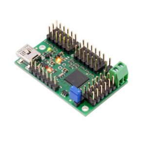
Pololu Mini Maestro 18-Channel USB Servo Controller (Assembled)
- ₹5,970
- Channels: 18 Baud: 300 ?? 200000 bps1 Minimum operating voltage: 5 V Maximum operating voltage: 16 V Supply current: 40 mA2
-
-
-
- Out of StockRead more
- Drivers, Motors, Pololu Motor Drivers, Pumps
Pololu Motor Driver and Power Distribution Board for Romi Chassis
- ₹5,450
- Can supply a continuous 2.5 A at 5 V or 3.3 V Two DRV8838 motor drivers
-
-
-
-
-
-
- Out of StockRead more
- Drivers, Motors, Pololu Motor Drivers, Pumps
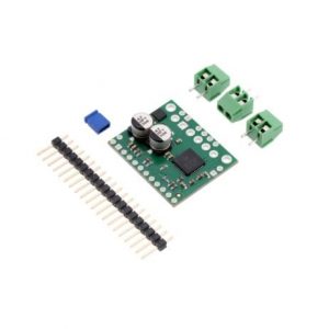
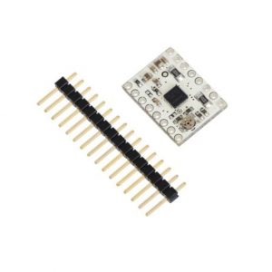
Pololu MP6500 Stepper Motor Driver Carrier, Potentiometer Current Control
- ₹1,461
- Built-in regulator (no external logic voltage supply needed) Can interface directly with 3.3?V and 5?V systems Over-temperature thermal shutdown, over-current shutdown, short circuit protection, and under-voltage lockout 4-layer, 2?oz copper PCB for improved heat dissipation
-
-
-
-
-
- Out of StockRead more
- Drivers, Motors, Pololu Motor Drivers, Pumps
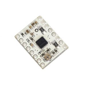
Pololu TB67S249FTG Stepper Motor Driver Compact Carrier
- ₹2,476
- Built-in regulator (no external logic voltage supply needed) Can interface directly with 3.3 V and 5 V systems Under-voltage lockout and protection against over-current/short-circuit and over-temperature Open-load detection Active-low error outputs indicate over-current, over-temperature, or open-load condition Compact size (0.6???×?0.8??) 4-layer, 2 oz copper PCB for improved heat dissipation
-
-
-
-
-
- Out of StockRead more
- Dimension Engineering Motor Drivers, Drivers, Motors, Pumps
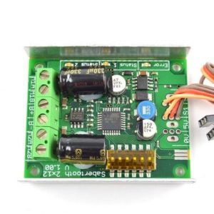
Sabertooth Dual 12A Motor Driver for R/C
- ₹5,889
- Synchronous regenerative drive Ultra-sonic switching frequency Thermal and overcurrent protection Lithium protection mode Dual motor driver Ultra-sonic switching frequency 1 Amp Switching BEC
-
-
-
-
-
-
- Out of StockRead more
- Dimension Engineering Motor Drivers, Drivers, Motors, Pumps
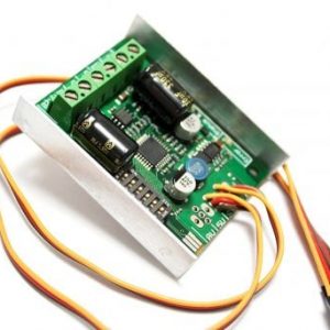
Sabertooth Dual 60A Motor Driver
- ₹18,461
- 60A continuous, 120A peak per channel 6-30V nominal, 33.6V absolute maximum Synchronous regenerative drive Ultra-sonic switching frequency Thermal and overcurrent protection Lithium protection mode
-
-
-
-
-
-
-
- Out of StockRead more
- Brushed / Brushless DC motor Driver, Drivers, Motors, Pumps
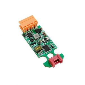
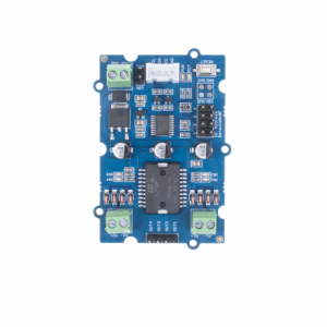
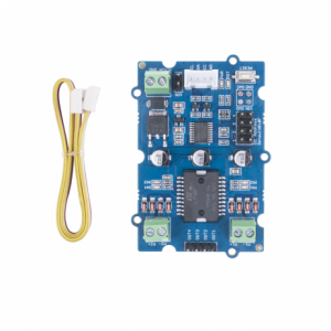
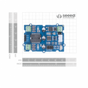
SeeedStudio Grove I2C Motor Driver (L298P)
- ₹1,769
- MCU: STM32f030f4P6 microcontroller Motor Supply Voltage:6-15V Output Current:2A(max) Logic Interface: I2C
-
-
-
-
-
-
-
- Out of StockRead more
- Brushed / Brushless DC motor Driver, Drivers, Motors, Pumps
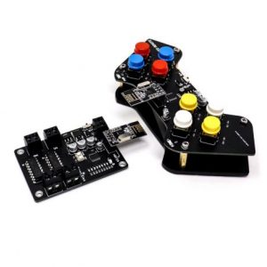
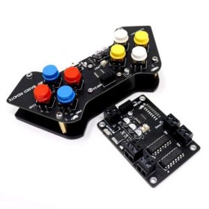
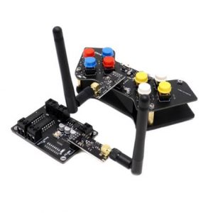
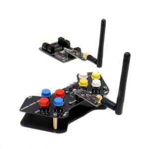
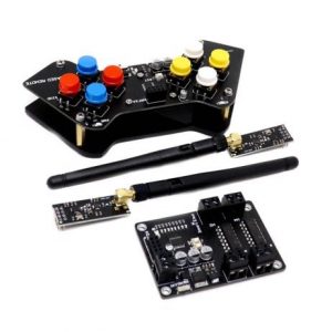
SmartElex Wireless Remote Control with NRF24L01 Transceiver Module
- ₹2,075
- Built-in 2.4Ghz antenna Number of Channel:? 4 Antenna Gain (peak): 2Dbi Built-in voltage regulator On-Board 9v battery socket on the remote sideboard
-
-
-

-
-
-
-
- Out of StockRead more
- Brushed / Brushless DC motor Driver, Drivers, Motors, Pumps
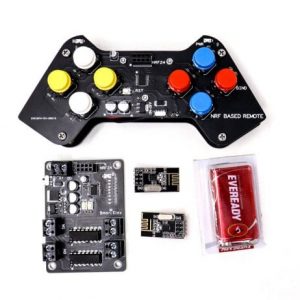
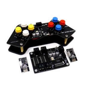
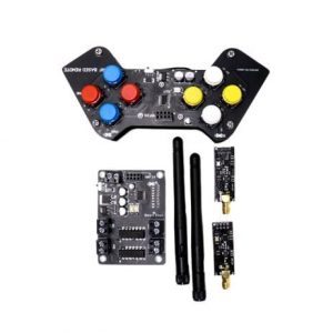
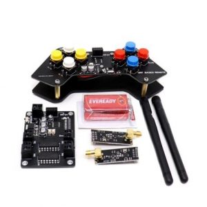
SmartElex Wireless Remote Control with NRF24L01+PA+LNA SMA Antenna
- ₹2,272
- It uses 2.4GHz global open ISM band, with license-free. Operating Range: 1Km Antenna Gain (peak): 2Dbi. Transmit power is greater than +20 dBm. Support six-channel data reception.
-
-
-
-
-
-
-
- Out of StockRead more
- Drivers, Motors, Pumps, Stepper Motor Drivers
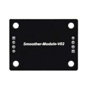
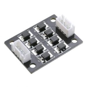
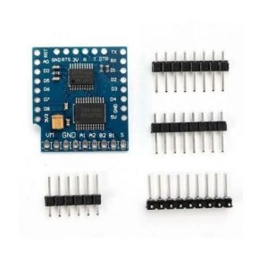
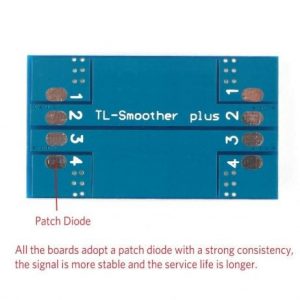
Smoother module for stepper driver motor
- ₹116
- Add-on module for stepper motors of 3D Printers. Compatibility: All types of FDM 3D Printers. Product Type: Smooth Reduced vibration ?Reduces noise emission and detailed results.
-
-
-
-
-
-
-
- Out of StockRead more
- Dimension Engineering Motor Drivers, Drivers, Motors, Pumps
SyRen 50A regenerative motor driver
- ₹10,501
- Nominal Voltage:6~30 V continuous Current:50A peak Current: 100A
-
-
-
- Out of StockRead more
- Brushed / Brushless DC motor Driver, Drivers, Motors, Pumps
TB6612 D1 Motor Driver Shield
- ₹813
- Interface: I2C Power supply voltage: VM = 15V max Output current: Iout = 1.2A ( average ) / 3.2A ( peak ) Standby control to save power CW / CCW / short brake / stop motor control modes Standby control mode-I2C mode: control TB6612??s STBY with I2C protocol IO mode: control TB6612??s STBY with Spin
-
-
-
-
- Out of StockRead more
- Drivers, Motors, Pumps, Stepper Motor Drivers
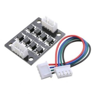
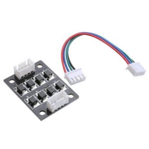
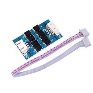
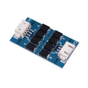
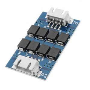
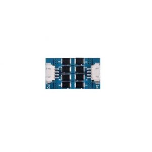
TL-Smoother Eight Chip Module DFORCE Vibration Pattern Filter with Cable
- ₹129
- TL Smoother can effectively eliminate the mechanical chatter generated by 3D printer motors, The TL-Smoother is an addon module for 3D printer stepper motor drivers. The board provides flyback diodes for the motor outputs, so they are also protected against inductance voltages in the unpowered state of the driver. You will get smoother movement, especially on the delta-style 3D printer…
-
-
-
-
-
-
-
- Out of StockRead more
- Drivers, Motors, Pumps, Stepper Motor Drivers
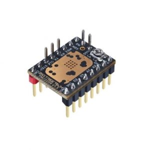
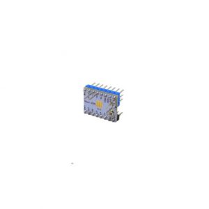
TMC2209 V3.0 Stepper Motor Driver Module
- ₹506
- Microstepping: Up to 1/256 micro stepping Maximum current: 2.8A RMS, 4.0A peak Voltage range: 4.75V to 28V DC Logic voltage: 3.3V and 5V compatible
-
-
-
-
-
- Out of StockRead more
- Drivers, Motors, Pumps, Stepper Motor Drivers
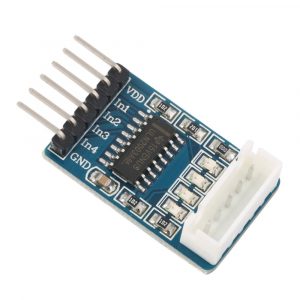
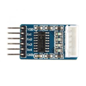
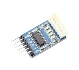
ULN2003A Driver Module Stepper Motor Driver
- ₹63
- 5-12V power supply 4-way signal indicator Chip all the pins have Input leads Mounted for easy connection to use XH-5P socket can be connected directly 28BYJ-48 Model stepper motor Dimensions: 32 x 18 x 11mm (LxWxH) Weight: 3 gm
-
-
-
-
-
-
- Out of StockRead more
- Cytron Motor Drivers, Drivers, Motors, Pumps
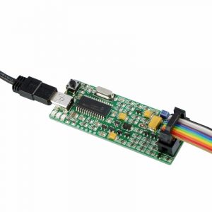
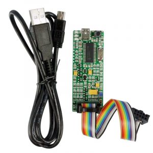
USB ICSP PIC Programmer UIC00B
- ₹1,297
- Program most of the +3.3V or +5V PIC Compatible with PICkit2??s UART Tool and Logic Tool The program most of the current 8-, 16-, and 32-bit Flash PIC microcontroller Compatible with Windows XP, Vista,?7, 8 and 8.1. Compatible with Microchip??s PICkit 2. Powered directly from the USB port. NO EXTERNAL POWER REQUIRED for UIC00B to function. Compatible with PICkit2??s Logic…
-
-
-
-
- Out of StockRead more
- Dimension Engineering Motor Drivers, Drivers, Motors, Pumps
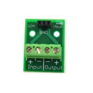
Voltage Regulator Breakout Board
- ₹897
- Product: Voltage Regulator Dimensions: 32.cm x 2.5cm x 1.2cm Weight: 6g Two mounting holes Operating Temperature: 0?C to 125?C
-
-
-
- Out of StockRead more
- Drivers, Motors, Pumps, Servo Motor Drivers
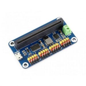
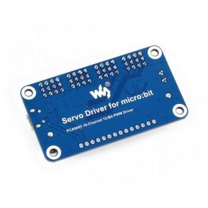
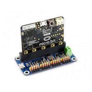
Waveshare 12-bit I2C 16-Channel Servo Driver for micro:bit
- ₹1,769
- Power supply: 5V (POWER connector)?OR?6V~12V (VIN terminal) Servo voltage: 5V Logic voltage: 3.3V Driver: PCA9685 Control interface: I2C Dimension: 65mm x 36mm Mounting hole size: 3.0mm
-
-
-
-
-
- Out of StockRead more
- Drivers, Motors, Pumps, Stepper Motor Drivers
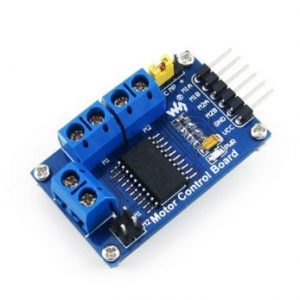
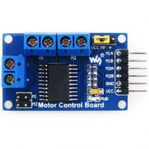
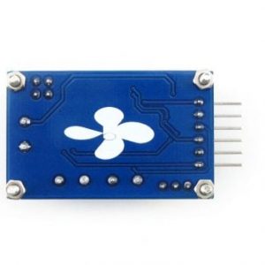
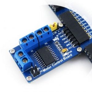
Waveshare Motor Control Board
- ₹589
- operating voltage:5V motor drive voltage:4.5V-36V Dimension : 43mm*27mm Mounting hole size: 2mm
-
-
-
-
-