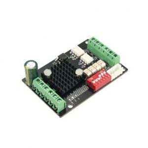
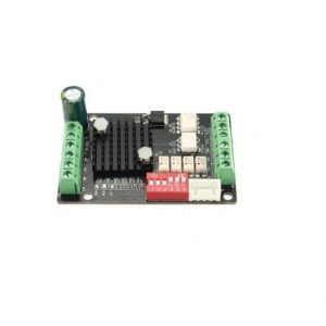
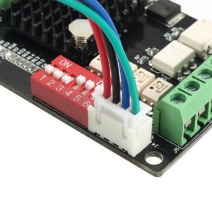
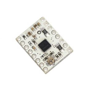
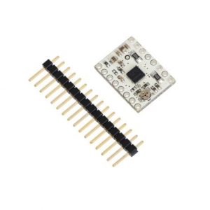
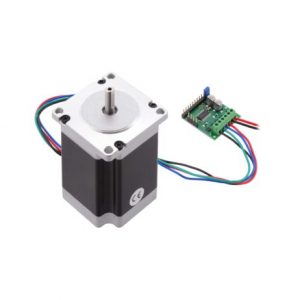
High-speed optocoupler, high-speed without losing a step LV8729 chip, with over-current protection circuit, the maximum support 128 segments Automatic half-flow function A variety of input methods to meet a variety of interface needs The use of increased heat sink, good heat dissipation
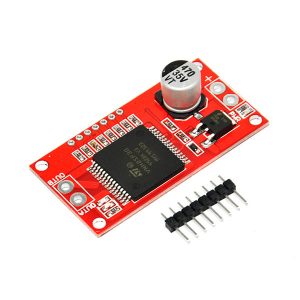
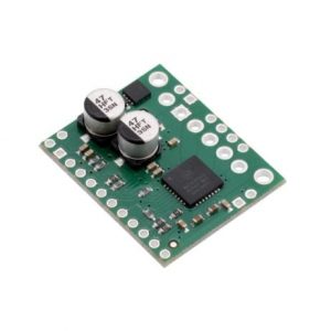
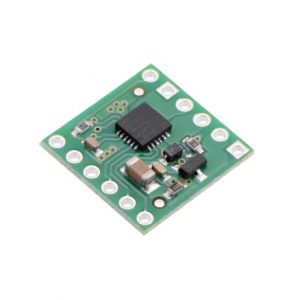
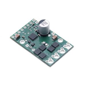
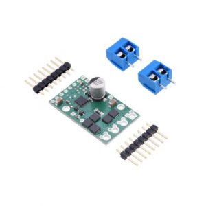
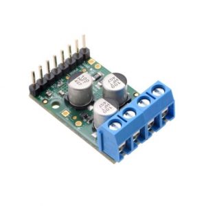
Voltage Max: 16V Maximum current rating: 30 A Practical Continuous Current: 14 A Current sensing available to Arduino analog pin MOSFET on-resistance: 34 mΩ Maximum PWM frequency: 10 kHz Thermal Shutdown Undervoltage and Overvoltage shutdown.
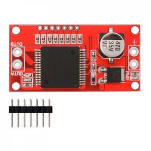
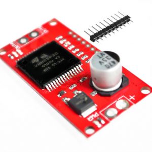
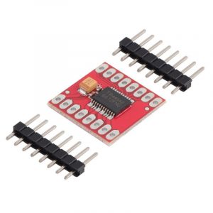
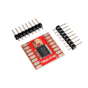
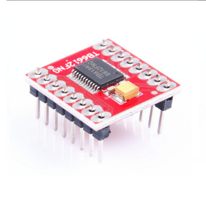
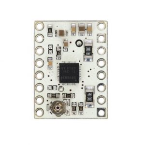
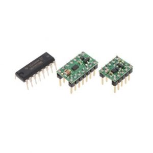
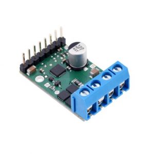
CW/CCW/short break/stop motor control modes Built-in thermal shutdown circuit and a low voltage detecting circuit Standby control to save power CW/CCW/short brake/stop motor control modes Operating Voltage(VDC): 15 Peak Current (A): 3.2 Continuous Current (A): 1.2 No. of Channels: 1
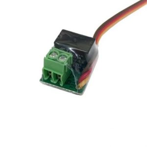
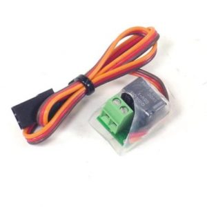
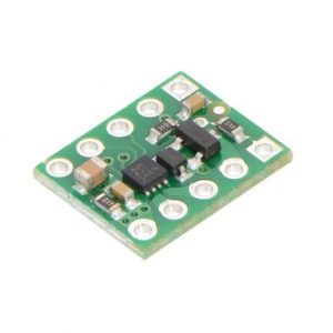
Product: Radio controlled relay Max relay voltage: 60VDC, 125VAC Max relay current: 1A at 24VDC, 0.5A at 125VAC (60W light-bulb) Relay resistance: 100 mO max Operating voltage: 3.5V to 5.5V
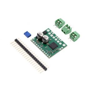
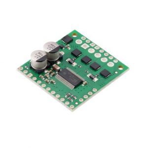
Compatible with 5?V and 3.3?V microcontrollers Integrated 5V regulator that can be used to supply an external microcontroller Integrated watchdog function Open coil detection Thermal warning indicates when the driver is close to the thermal shutdown temperature Over-current status and shutdown (short-to-ground and shorted-load protection) Reverse voltage protection
Under-voltage lockout on the logic supply and protection against over-temperature Carrier board adds reverse-voltage protection on the motor supply Compact size (0.6??×0.6??) Built-in under-voltage and over-temperature protection
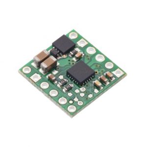
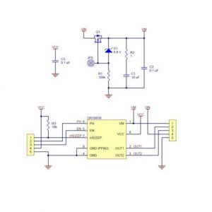
built-in protection against reverse-voltage, under-voltage, over-current, and over-temperature simple two-pin speed direction interface Under-voltage lockout and protection against over-current and over-temperature Simple interface requires only two I/O lines (one for direction and another for speed)
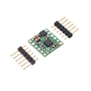
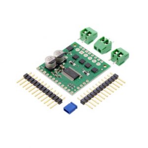
Built-in regulator (no external logic voltage supply needed) Short-to-ground, short-to-supply, and shorted-load protection 4-layer, 2?oz copper PCB for improved heat dissipation Exposed solderable ground pad below the driver IC on the bottom of the PCB Simple step and direction control interface
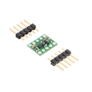
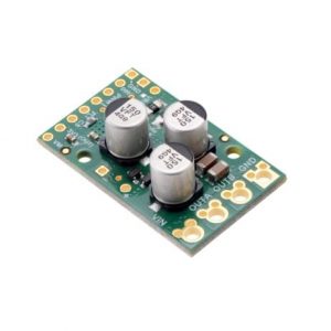
Reverse-voltage protection on the motor supply H-bridge motor driver: can drive one DC motor Motor supply voltage: 0?V to 11?V Logic supply voltage: 1.8?V to 7?V easy to use with standard solderless breadboards
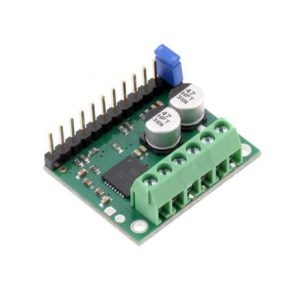
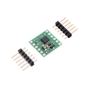
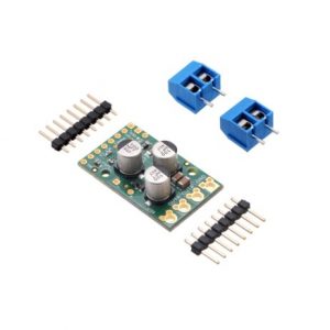
Reverse-voltage protection Short circuit protection Current sensing and current limiting functionality Inputs compatible with 1.8?V, 3.3?V, and 5?V logic
Inputs compatible with 1.8?V, 3.3?V, and 5?V logic Under-voltage lockout, over-current protection, short circuit protection, and reverse-voltage protection (up to 40?V) High-power: can deliver up to 4?A continuous per phase without extra cooling (6?A max with sufficient additional cooling) Highly configurable through SPI interface Optional STEP/DIR control pins (stepping can also be controlled through SPI interface alone)